RAVENFORGE / SIGNAL & TRANSDUCTION RESEARCH LOG — A06
RAVENFORGE
Signal & Transduction Research Log
A06 — Onboard Preamp Architecture
Designing gain · mixing · EQ · output after the pickup-facing boundary as a single low-Z signal system
Document purpose |
Code | A06 |
|---|---|
Focus | onboard preamp architecture · pickup isolation · mixing · gain structure · EQ/filter law · output boundary · power/bypass |
Evidence | manufacturer technical documentation · analog circuit application notes · pickup modeling literature · RavenForge synthesis |
RavenForge link | A05 active boundary → A06 onboard architecture → B06 internal signal path → A07 headroom/power |
Upstream logs | A03 · A04 · A05 · B03 |
Downstream logs | B06 · A07 · A08 · C03/C04 (experiment deferred) |
Status | Literature / technical verification complete · architecture framework established · prototype measurement pending |
Date | 2026-09-18 |
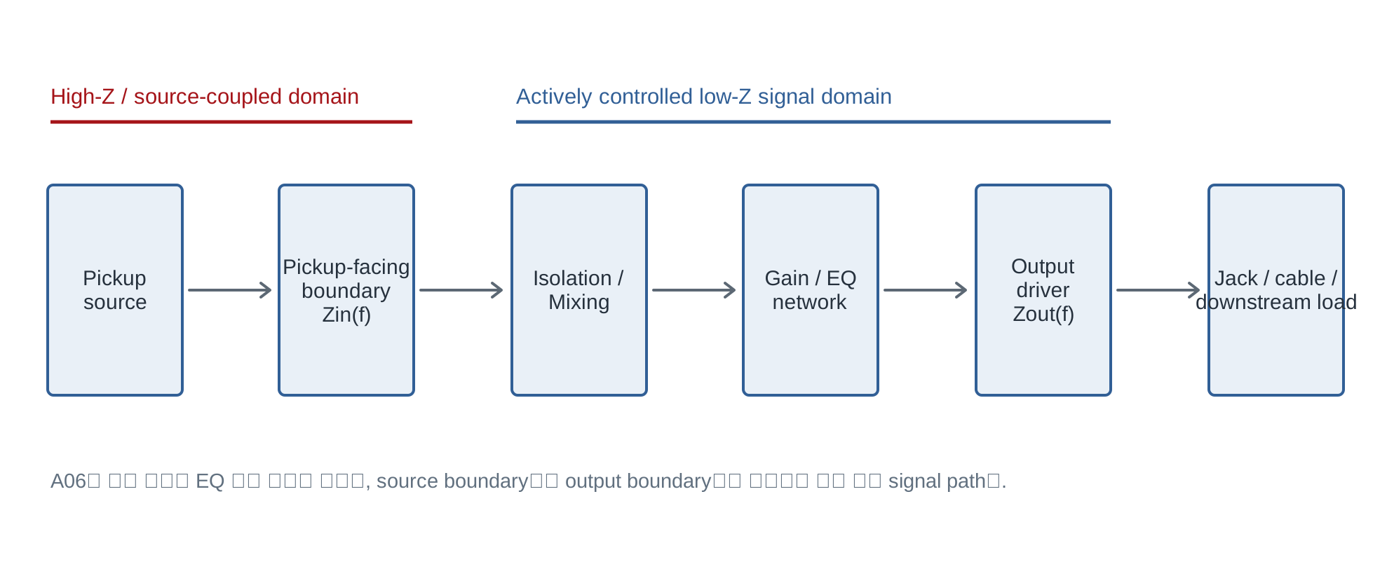
Figure 1. A06 system boundary. The design object of an onboard preamp is not a single EQ module, but the entire active signal domain extending from the pickup-facing boundary to the output boundary.
1. Research question — Where does an “active bass” actually become active?
Reducing instruments with onboard preamps to a simple passive/active binary hides important structural differences. A system may retain passive pickups and a passive volume/blend network and make only the EQ active; it may place a buffer immediately after the pickup to define source loading; or it may buffer each pickup independently before active mixing. Systems such as the John East UNI-PRE even maintain independent active and passive paths and provide a separate FET input stage and gain trim for each pickup [6].
A06 Core Position |
2. Architecture taxonomy — Classify by signal path, not by product name
The Type I–V scheme below is not an industry-standard taxonomy; it is a RavenForge working taxonomy for structural comparison. Its purpose is not to rank products, but to state explicitly which loading and pickup interactions are preserved and which interactions are isolated.
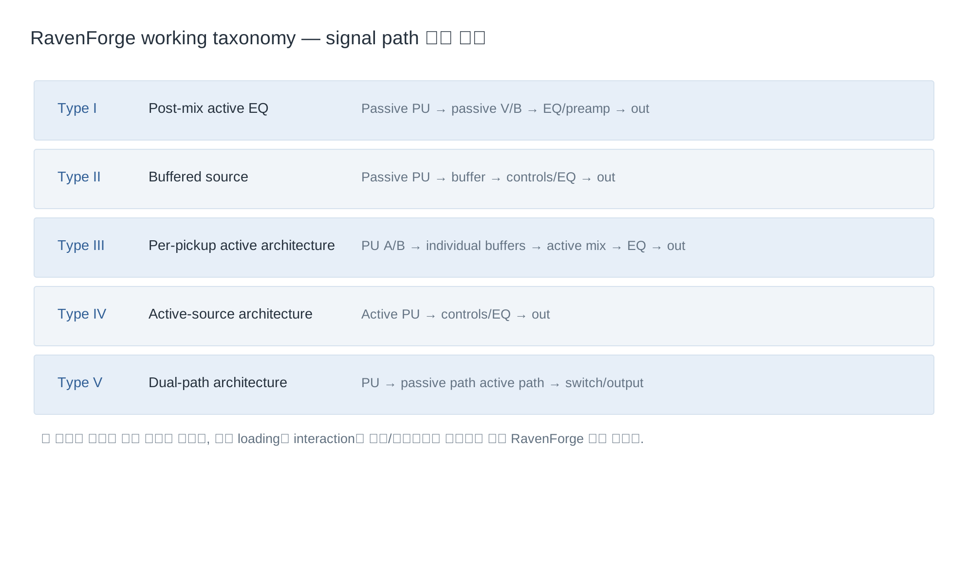
Figure 2. RavenForge working taxonomy. Even among instruments called “active basses,” the point at which the active domain begins and the mixing method can differ.
Type | Signal path | Design meaning |
|---|---|---|
I — Post-mix active EQ | Passive PU → passive V/B → EQ/preamp → out | Only the downstream section is made active while retaining the existing pickup/pot interaction |
II — Buffered source | Passive PU → buffer → controls/EQ → out | Explicitly defines the pickup-facing load with the buffer input |
III — Per-pickup active | PU A/B → individual buffers → active mix → EQ → out | Reduces electrical interaction between pickups and enables gain matching |
IV — Active-source | Active PU → controls/EQ → out | The source itself already contains a low-Z active stage |
V — Dual-path | PU → passive path ∥ active path → output | Maintains the passive reference and active path separately |
The UNI-PRE is a representative example that combines characteristics of Type III and Type V. The manufacturer states that its active and passive volume/blend paths are completely independent, and that in the active path each pickup has its own input buffer/amplifier and 0–12 dB gain trim [6]. This allows pickups with different output levels to be level-matched within the active path.
3. Input boundary — Zin is not merely a compatibility number
From the A03–A05 perspective, a passive magnetic pickup is not a zero-impedance voltage source but a resonant source with frequency-dependent source impedance ZPU(f). The preamp input impedance Zin(f) is therefore not a transparent number that simply “accepts” the pickup; it is one of the boundary conditions that determines the damping of the loaded resonance [1,9].
Product | Published input impedance | Interpretation boundary |
|---|---|---|
Darkglass Tone Capsule | 500 kΩ | Official specification for this product [2] |
ZUTA Bass Core | 1 MΩ | Official specification for this product [7] |
Aguilar OBP-3 | 1 MΩ | Official specification for this product [3] |
Bartolini NTMB+FL | 400 kΩ | Official specification for this product [4] |
EMG BQC | 1 MΩ | Official specification for this product [5] |
John East UNI-PRE | No published value confirmed | Value is not inferred [6] |
The generalization “higher Zin = better sound” is inappropriate. A higher Zin generally reduces resistive damping of the pickup resonance, but if a pickup/network is intentionally voiced into a 250–500 kΩ load, moving it to a 1 MΩ buffer is itself a different tonal condition. A06 records Zin as a voicing parameter, not as a quality ranking.
4. Pickup mixing — A blend pot alone does not describe the topology
In a passive blend, each pickup’s source impedance and the blend/volume pots form one network, so the control position of one pickup can affect the load seen by the other pickup and the resulting mixed response. If each pickup is buffered independently before mixing, the mixer instead handles low-Z sources, greatly reducing mutual loading between the pickups themselves.
The UNI-PRE’s dual active/passive path description shows this distinction clearly at product level. The manufacturer explains that in active mode each pickup passes through an independent input buffer/amplifier, isolating the pickups from one another and enabling smooth blending and pickup level matching [6].
Specification rule |
5. Gain structure — EQ boost and “preamp gain” are not the same thing
If gain is collapsed into a single number in an onboard system, it becomes difficult to trace where clipping occurs. For analysis, it is more useful to separate source level → input gain → mixing/summing → EQ gain → output stage. The Bartolini NTMB+FL provides an internal 0–12 dB gain trim separate from EQ boost/cut, while the UNI-PRE also provides 0–12 dB active gain trim for each pickup [4,6].
In a system that uses large EQ boosts, the available swing may be exceeded in a stage after the EQ even when the input stage itself is not clipping. A06 therefore specifies not only overall gain but stage-by-stage gain allocation, worst-case cumulative boost, and the point chosen as the reference level.
6. EQ architecture — Three knobs define a reachable tonal space, not merely three numbers
Product | Published EQ specification | Architectural meaning |
|---|---|---|
Darkglass Tone Capsule | 70 Hz ±12 dB / 500 Hz ±12 dB / 2.8 kHz ±12 dB | High-mid control instead of conventional treble [2] |
ZUTA Bass Core | <40 Hz approx. ±16 dB / selectable mid approx. ±15 dB / >3.25 kHz approx. ±12 dB | 6-way mid-target selection; manufacturer neutral ±0.5 dB claim [7] |
Bartolini NTMB+FL | 30 Hz ±12 dB / 250 Hz ±12 dB / 6.5 kHz ±15 dB | Separate 0–12 dB gain trim [4] |
Aguilar OBP-3 | 40 Hz ±18 dB / 400 or 800 Hz ±16 dB / 6.5 kHz ±16 dB | Selectable mid center [3] |
EMG BQC | Bass ±12 dB @20 Hz / sweepable mid 100 Hz–1 kHz / adjustable treble | Active/passive pickup input; 18 V recommended [5] |
John East UNI-PRE | Bass window + sweep mid 100 Hz–2.5 kHz + adjustable treble shelf | Internal adjustment of pickup gain, pre-shape, and EQ voicing [6] |
These differences do not mean that one frequency is “better” than another. Using a 2.8 kHz high-mid control instead of conventional treble, as in the Tone Capsule, changes the tonal operations available to the player. A sweepable mid or selectable center frequency expands the reachable state-space. An ideal EQ specification should therefore include not only center/corner frequency, but also shelf/peaking behavior, Q or slope, boost/cut range, and control law.
TI SLOA042 describes one implementation of a classic Baxandall-type active tone control in which the frequency-setting network is placed in the op-amp feedback loop [10]. The existence of that literature does not justify classifying every onboard preamp as Baxandall. Internal filter topology is not inferred for products without a manufacturer schematic or other reliable circuit documentation.
7. Active-flat ≠ Passive bypass — Separate the reference states
Putting the EQ controls at their center detents does not make the active signal path disappear. ZUTA claims that the Bass Core affects 20 Hz–20 kHz by no more than ±0.5 dB with all knobs neutral, yet it is still an active circuit with a 1 MΩ input and 1 kΩ output [7]. Even when the frequency magnitude is nearly flat, source loading, noise, maximum signal swing, output impedance, and downstream coupling already differ from the passive path.
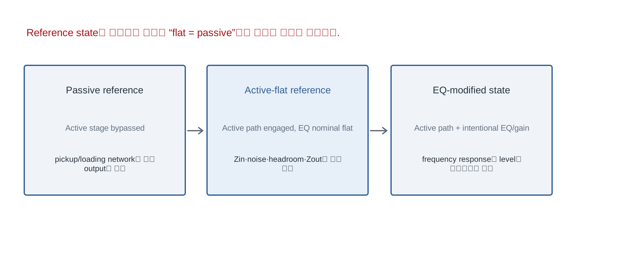
Figure 3. A06 reference-state model. Meaningful comparison requires separating the passive reference, active-flat reference, and EQ-modified state.
Reference state | Definition | Comparison caution |
|---|---|---|
Passive reference | Passive path that does not pass through the active stage | Retains the original pickup/pot/cable loading |
Active-flat reference | Passes through the active path while EQ transfer is nominally flat | Zin, noise, headroom, and Zout have already changed |
EQ-modified state | State with intentional active EQ/gain modification | Response and level may change together |
8. Output boundary — The preamp redefines the instrument as a low-Z source
Published output impedances include 1 kΩ for the Tone Capsule, 1 kΩ for the ZUTA Bass Core, 2 kΩ for the EMG BQC, and 100 Ω for the Aguilar OBP-3 [2,3,5,7]. These low-Z outputs create a source condition that is less sensitive to downstream cable/load effects than a passive magnetic pickup directly coupled to a long cable capacitance.
However, saying that “cable effects disappear” is too strong. The cable remains a load that the output stage must drive, and actual closed-loop Zout and capacitive-load stability depend on frequency and circuit topology. A06 records output impedance and recommended minimum load as separate specifications. ZUTA recommends a load of at least 10 kΩ [7].
9. 9 V / 18 V — An operating condition, not a tone adjective
Using 18 V does not automatically “improve sound quality.” In a single-supply analog stage, supply voltage is one factor that sets the upper limit of possible signal swing, but actual usable swing is constrained by the device input common-mode range, output swing, bias point, load current, closed-loop gain, and distortion criterion.
Analog Devices AN-581 explains that biasing the output near midsupply is a common way to obtain the maximum bidirectional swing from a given single supply, and notes that a simple resistor-divider bias can create power-supply-rejection and stability problems [8]. EMG likewise recommends 18 V operation for the BQC under strong playing and bass/treble boost conditions [5].
A06 boundary |
10. Power · noise · bias — The battery is part of the signal architecture
In an onboard system, the battery and bias/reference network cannot be treated as conditions outside the instrument. The Tone Capsule publishes current consumption of about 2.4 mA, while the EMG BQC specifies 600 µA at 9 V and 740 µA at 18 V [2,5]. Low current draw benefits battery life, but low power does not automatically imply low noise, high headroom, or wide bandwidth.
The virtual reference and decoupling of a single-supply stage directly affect transfer and stability. AN-581 explains that if a midsupply divider is not adequately bypassed, supply variation can enter the signal path through the reference and degrade PSR, and that instability can occur under large output-current conditions [8]. Architecture documentation should therefore include reference topology, decoupling, current draw, and turn-on behavior as well as supply voltage.
11. Published examples — Not all “3-band preamps” share the same architecture
System | Zin | Zout | Structurally verifiable features |
|---|---|---|---|
Darkglass Tone Capsule | 500 kΩ | 1 kΩ | 70 / 500 / 2.8k, 9–18 V, ~2.4 mA [2] |
ZUTA Bass Core | 1 MΩ | 1 kΩ | dual-stage, selectable mid, neutral ±0.5 dB claim, ≥10 kΩ load [7] |
Bartolini NTMB+FL | 400 kΩ | Not disclosed | 0–12 dB gain trim + 3-band EQ, 9/18 V [4] |
Aguilar OBP-3 | 1 MΩ | 100 Ω | discrete FET input, selectable 400/800 Hz mid, 9/18 V [3] |
EMG BQC | 1 MΩ | 2 kΩ | active/passive pickup input, sweep mid, 18 V recommended [5] |
John East UNI-PRE | Not disclosed | Not disclosed | independent active/passive paths, per-pickup FET stage + gain trim [6] |
An important principle is not to fill unpublished values by inference. Values such as the UNI-PRE Zin/Zout or the Bartolini NTMB+FL Zout remain unknown when they cannot be confirmed in official documentation. Manufacturer language such as “transparent,” “high headroom,” and “studio-quality” is also kept distinct from independently measured fact.
12. Myth audit — Claims to retain, revise, or remove from the draft
Claim | Action | Evidence / caution |
|---|---|---|
An onboard preamp is not merely an EQ | Retain | Real products exist that include input, mixing, gain, output, and power functions |
Higher Zin is always better | Remove | Loaded response depends on source voicing and intended load |
Passive blend and buffered blend are identical | Remove | The pickup-to-pickup loading architecture differs |
Every preamp follows input → mix → EQ → out | Revise conditionally | Actual stage order and control placement vary by product |
The OBP-3 uses a Baxandall topology | Remove | Filter topology cannot be inferred without published evidence |
Active-flat = passive | Remove | The Zin/Zout/noise/headroom boundary differs |
18 V always improves sound quality | Remove | Treat it as a supply/headroom operating condition |
18 V provides exactly twice the usable headroom | Remove | Depends on device, bias, load, and clipping criterion |
A FET input is automatically low-noise | Remove | Source impedance and voltage/current noise must be evaluated together |
13. RavenForge Onboard Electronics Specification Bundle
Specification chain |
Area | Required record |
|---|---|
Source | passive / active pickup, nominal output, source Z(f) |
Input | Zin, input capacitance or input network |
Isolation | none / common buffer / per-pickup buffer |
Mixing | passive blend / buffered blend / active summing |
Gain | input / pickup trim / mix / EQ / output gain |
EQ | topology (when verifiable), frequency, Q/slope, boost/cut range, control law |
Reference | define passive / active-flat / shaped state |
Dynamic | supply, maximum input/output, clipping criterion |
Output | Zout, recommended minimum load |
Noise | input-referred or output noise, measurement bandwidth/weighting |
Power | supply range, current draw, battery switching, reference/decoupling |
Bypass | true passive / buffered bypass / no bypass |
Validation | published spec / bench measurement / prototype-specific acceptance threshold |
14. Application to RavenForge models
The most important design principle from A06 is not to rank preamps simply by price. Treating different modules such as ZUTA, Noll, and John East only as “Standard → Upgrade → Premium” hides architectural differences. A system such as the UNI-PRE, with per-pickup buffering and independent active/passive paths, changes the topology by much more than merely replacing an EQ module.
In a design such as ASKR, where the source itself is an active pickup, the Zin problem cannot be applied in the same way as with a passive magnetic pickup. Conversely, if pickup interaction and passive filtering are deliberately part of the voice, as in EDDA, a buffer placed immediately after the pickup may remove the intended coupled behavior. In EMBLA as well, “preamp selection” becomes a boundary choice depending on the pickup and the placement of passive controls.
RavenForge design rule |
15. Claim-by-Claim Evidence Matrix
Claim | Direct evidence | Evidence level | Caution |
|---|---|---|---|
An onboard preamp can include input/output/gain architecture in addition to EQ | UNI-PRE, NTMB+FL, BQC manufacturer documentation [4–6] | High | Does not mean all products share the same architecture |
Zin varies from 400 kΩ to 1 MΩ or more across products | Official Darkglass/ZUTA/Aguilar/Bartolini/EMG specifications [2–5,7] | High | Limited to the stated models |
Per-pickup buffering reduces direct loading between pickups | UNI-PRE manufacturer circuit description + circuit theory [6] | High | Actual mixed response also depends on downstream topology |
Active-flat is not the same as passive bypass | Published Zin/Zout and active-path architecture [2,5,7] | High | The effect size of any “audibly different” result requires separate measurement |
Usable headroom cannot be determined exactly from supply voltage alone | AN-581 [8] | High | Device-specific datasheets and load conditions are required |
The frequency allocation of EQ controls defines the reachable tonal space | Official product EQ specifications [2–7] | Medium–High | Does not imply a sonic ranking |
Not every onboard preamp can be treated as Baxandall | The TI literature describes only a particular Baxandall implementation [10] | High | Topology remains unknown for products without published circuitry |
Battery/reference/decoupling affect stability and transfer | AN-581 [8] | High | Prototype implementation requires later validation |
16. Research boundary and subsequent logs
A06 establishes only the architecture and specification language. A07 — 9V vs. 18V: Headroom and Dynamic Range will treat supply voltage, rail margin, clipping, and signal level separately. B06 — Rethinking the Internal Signal Path will extend the stages and boundaries defined here into the actual internal control/routing architecture of the instrument.
C03 — Preamp Frequency Response Mapping will measure EQ curves, active-flat response, gain, and output response, while C04 — Headroom Test will validate 9/18 V maximum swing, THD+N, and clipping threshold. In accordance with the current master-schedule policy, the C-series experiments are deferred to a later phase.
17. Source status / interpretation boundary
Product values in this log prioritize manufacturer and official technical documentation. Terms such as “transparent,” “high headroom,” and “studio-quality” are treated as manufacturer claims, not as independently measured facts. ZUTA’s neutral ±0.5 dB and +20 dBu input-level figures are likewise manufacturer-published specifications [7].
The op-amp type, filter topology, Q, and internal gain distribution of products without published schematics are not inferred. This document is an architecture study based on literature, circuit theory, and published specifications; it does not contain RavenForge prototype measurements. Actual effect sizes and acceptance thresholds will be determined in later C-series work.
18. Current conclusion — The onboard preamp is a signal-domain architecture
Current conclusion |
The defining issue is not whether a preamp “has a 3-band EQ.” A06 asks where the source is isolated, how signals are mixed, at which stage gain is created, what tonal state-space is made available, and through what dynamic/output boundary the signal leaves the instrument. RavenForge will therefore document onboard electronics as signal architecture and a measurable specification bundle rather than as a component list.
References
[1] RavenForge. A05 — Active Buffers and Input Impedance. Signal & Transduction Research Log, 2026-09-14.
[2] Darkglass Electronics. “B2M2 Tone Capsule.” Official product specifications: 500 kΩ input, 1 kΩ output, ~2.4 mA, 70 Hz / 500 Hz / 2.8 kHz ±12 dB, 9–18 V. https://www.darkglass.com/products/tone-capsule
[3] Aguilar Amplification. “OBP-3 — 3 Band, Boost/Cut, 9 or 18 Volt On Board Preamp.” Official specifications: 1 MΩ input, 100 Ω output, 40 Hz ±18 dB, 400/800 Hz ±16 dB, 6.5 kHz ±16 dB. https://aguilar.korg-kid.com/obp
[4] Bartolini. “NTMB+FL 3-Band EQ Preamp Module.” Official specifications: 400 kΩ input, 0–12 dB gain trim, 30 Hz ±12 dB, 250 Hz ±12 dB, 6.5 kHz ±15 dB, 9/18 V. https://bartolini.net/product/ntmbfl/
[5] EMG Pickups. “BQC Control — Active / Passive Pickup Input.” Installation Information 0230-0203K. 1 MΩ input, 2 kΩ output, 600/740 µA @ 9/18 V, 18 V recommended. https://www.emgpickups.com/pub/media/Mageants/b/q/bqc_control_b245_0230-0203rk.pdf
[6] East UK / John East. “UNI-PRE User Manual.” Independent active/passive paths; per-pickup Class-A FET input stages; 0–12 dB pickup gain; EQ details. https://www.east-uk.com/2025/11/28/uni-pre-5-knob-user-manual/
[7] ZUTA Group. “ZUTA Bass Core.” Official product specifications: 1 MΩ input, 1 kΩ output, recommended load ≥10 kΩ, dual-stage analog circuit, selectable mid, manufacturer neutral-response claim ±0.5 dB (20 Hz–20 kHz), 9–18 V. https://zutagroup.com/products/zuta-bass-core
[8] Kitchin, C. “AN-581: Biasing and Decoupling Op Amps in Single Supply Applications.” Analog Devices. https://www.analog.com/en/resources/app-notes/an-581.html
[9] Paiva, R. C. D.; Pakarinen, J.; Välimäki, V. “Acoustics and Modeling of Pickups.” Journal of the Audio Engineering Society, 60(10), 768–782, 2012. https://aes.org/publications/elibrary-page/?id=16551
[10] Harris, D. “Audio Tone Control Using the TLC074 Operational Amplifier.” Texas Instruments Application Report SLOA042, 2000. https://www.ti.com/lit/an/sloa042/sloa042.pdf