RAVENFORGE / SIGNAL & TRANSDUCTION RESEARCH LOG — B06
RAVENFORGE
Signal & Transduction / Electronics Architecture Research Log
B06 — Rethinking the Internal Signal Path
통합 검증판 — stage order · impedance boundary · source domain · routing state · programmable switching
문서 목적 |
| Code | B06 |
|---|---|
| Focus | internal routing · source domains · reference states · Eshtronic evidence audit · piezo/magnetic integration · programmable switching · serviceability |
| Evidence | manufacturer datasheets/manuals · current product pages · historical review · circuit application notes · owner-community secondary evidence |
| Verification rule | current specification / historical implementation / RavenForge engineering inference를 분리하고, 불확실한 topology는 추정하지 않음 |
| RavenForge link | B03 passive architecture → A06 active architecture → B06 verified routing architecture → A07 headroom/power |
| Status | Deep-research verification revision · literature/technical synthesis complete · prototype measurement pending |
| Date | 2026-09-21 |
1. 연구 질문과 검증 개정의 목적
B06의 핵심 질문은 단순하다. 악기 내부 전자계를 항상 Pickup → Volume → Preamp/EQ → Output이라는 하나의 직렬 chain으로 설명해야 하는가? 심층 자료 검증 결과, 그렇게 일반화할 근거는 없다. 서로 다른 source는 서로 다른 input boundary를 요구할 수 있고, mode switch는 branch를 선택·우회·병합하며, 일부 state는 reference path를 별도로 만든다.
이번 개정은 기존 B06의 설계 프레임을 유지하되, 제조사 공식 사실 / 역사적 구현 / 사용자 커뮤니티 증언 / RavenForge의 engineering synthesis를 분리한다. 또한 “10 MΩ이 모든 piezo의 정답”, “25 kΩ이 모든 active pickup의 정답”, “현행 Eshtronic도 과거와 동일한 4-state routing”처럼 자료 범위를 넘어서는 문장은 제거하거나 조건부로 수정한다.
2. 조사 방법과 Source Hierarchy
| Level | 자료 유형 | B06에서의 사용 방식 |
|---|---|---|
| A | 제조사 datasheet / installation manual / current product page | 수치·현재 사양의 1차 근거 |
| B | 전문 technical application note / circuit theory | source impedance, switching, conditioning 원리 검증 |
| C | 당시 제품 리뷰 / archive | 역사적 Eshtronic 구현을 세대 한정 사례로 사용 |
| D | Bassic / TalkBass owner testimony | 반복되는 historical description의 보조 근거만 제공 |
| E | RavenForge synthesis | routing taxonomy와 specification framework; 제조사 사실로 표현하지 않음 |
심층 조사 중 B06과 직접 관련 없는 Stenback 자료가 검색 결과에 섞였지만, 내부 routing/electronics 검증 근거로는 채택하지 않았다. 관련성이 없는 자료를 근거 목록에서 배제하는 것도 evidence hygiene의 일부다.
3. Executive Verification Summary — 핵심 주장별 상태
| 주장 | Status | 검증 결과 |
|---|---|---|
| EMG 35/40-series active bass pickups의 output impedance는 10 kΩ이다 | Confirmed | EMG 공식 35/40 datasheet에서 확인 [5–6] |
| ESH의 현행 Stinger 계열은 Eshtronic, Mode Selector, piezo bridge를 사용한다 | Confirmed / option-dependent | ESH 공식 product pages에서 확인하되 세부 pickup 구성은 model/string-count option별로 기록 [2–3] |
| 과거 Eshtronic에는 Direct/Studio, magnetic+controls, magnetic+piezo, piezo-only 성격의 4-state 구현이 있었다 | Partially confirmed | 당시 리뷰와 복수 owner description이 일치하지만 현행 회로와 동일하다는 공식 근거는 없음 [4,11–12] |
| McGrath 12-Way Rotary Selector는 3픽업을 relay로 전환하고, 12개 기본 routing state·favorite/previous recall·All-Parallel failsafe를 제공하며 앱에서 14개 tonal possibility를 재배치할 수 있다 | Confirmed | McGrath 제조사 공개 자료와 Fret Nation 제품 사양에서 확인 [14–16] |
| EMG-equipped Studio/Direct state를 passive라고 부를 수 있다 | Contradicted | pickup 내부 active electronics가 남으므로 direct-source reference가 더 정확함 [5–6] |
| Piezo는 high-Z input이 중요하다 | Confirmed | TI와 Fishman 자료가 원리를 지지 [8–9] |
| 모든 passive piezo에 정확히 10 MΩ이 필요하다 | Contradicted as universal claim | 10 MΩ은 특정 Fishman source의 권장값; 일반 원리는 source/network-specific high-Z matching |
| B125는 pickup별 input buffer로 active/passive source 혼합을 지원한다 | Confirmed | EMG 공식 시스템 문서 [7] |
| 일부 Esh에 separate/direct piezo output이 존재했다 | Unverified for general use | owner-community evidence는 있으나 전 세대/현행 사양으로 일반화 불가 [11–12] |
3A. Stage-order & Impedance-Boundary Study — 기존 B06의 두 번째 축
Source-domain과 routing-state 검증만으로는 onboard electronics의 전체 구조를 설명할 수 없다. 같은 pickup, volume, tone, boost를 사용해도 high-Z pickup domain이 어디에서 끝나는지, volume이 active stage의 앞·뒤·사이에 놓이는지, filtering이 mixing 전인지 후인지에 따라 실제 electrical behavior가 달라질 수 있다. 따라서 통합 B06은 stage order / impedance boundary와 state-dependent routing을 서로 다른 두 축으로 함께 기록한다.
Unified B06 question |
3A.1 Stage order가 달라지는 회로적 이유
Passive magnetic pickup을 주파수 의존 source impedance ZPU(f)를 가진 source로 보면 다음 stage 입력에 전달되는 전압은 Vin(f)=Vs(f)×Zin(f)/[ZPU(f)+Zin(f)]로 표현할 수 있다. 따라서 active stage나 volume/tone network를 이동해 pickup이 보는 Zin(f)을 바꾸면 loaded resonance와 control interaction도 달라질 수 있다.
반대로 두 stage가 충분히 격리된 linear time-invariant block이고 서로의 loading을 무시할 수 있다면 H1(s)H2(s)=H2(s)H1(s)로 일부 순서 교환이 근사적으로 성립할 수 있다. 실제 악기에서는 finite Zin/Zout, potentiometer loading, noise contribution, clipping/headroom, nonlinear stage, feedback, source summing과 state-dependent switching 때문에 일반적으로 물리적 순서가 완전히 등가라고 가정할 수 없다.
3A.2 ZUTA CORE — active boundary before master volume
ZUTA CORE 공식 설치 매뉴얼의 권장 체인은 개념적으로 Pickup(s) → Selector / passive tone → CORE → Master Volume → Jack이다 [17]. 따라서 CORE를 post-volume booster로 분류하는 것은 맞지 않는다. 설계적으로는 passive selector/tone interaction을 CORE 앞에 남긴 뒤 active boundary를 만들고, master volume을 그 뒤에 두는 pre-volume active architecture다.
ZUTA LUXE의 1 MΩ input / 1 kΩ output 같은 공개 수치는 LUXE model-specific specification이다 [18]. 같은 계열이라는 이유로 CORE에 자동 전이하지 않는다.
3A.3 Fender Blackie / Elite MDX / Eric Clapton Signature — 역사와 topology를 분리한다
원조 Blackie는 active mid-boost가 장착된 기타가 아니며, 후대 Eric Clapton Signature electronics와 동일한 회로로 취급할 수 없다 [20]. Fender의 Clapton service diagram은 50 kΩ Audio Volume, 250 kΩ Mid Boost control, TBX 계열 dual control, circuit-board assembly와 9 V power를 공식적으로 확인시킨다 [19].
다만 first active stage → 50 kΩ volume → second mid-emphasis stage라는 내부 stage order는 Fender service layout 자체가 아니라 Aion FX와 같은 secondary circuit reconstruction에서 확인되는 해석이다 [22]. James Demeter·John Carruthers와 1983 Elite MDX에서 Clapton signature로 이어지는 역사적 설명도 secondary technical history로 구분한다 [21].
3A.4 EMG SPC/RPC — “stage order는 항상 중요하다”의 반례
EMG SPC/RPC 공식 installation information은 buffered active control을 signal path에 series로 배치하며, 일부 3-pickup wiring examples에서 Switch → Volume → Passive Tone → SPC → Jack과 Switch → Passive Tone → SPC → Volume → Jack을 모두 제시한다 [23]. 해당 문서는 두 예의 차이가 control order뿐이며 같은 결과를 낸다고 설명한다.
이 결과는 모든 low-Z circuit에 일반화할 수 없다. 해당 stage들의 linearity, Zin/Zout 관계와 control network 조건에서 성립하는 manufacturer-specific equivalence다. B06의 정확한 결론은 “order always matters”가 아니라 moving a stage가 loading, nonlinear operating level, summing law, filter interaction 또는 state routing을 바꾸는 경우 order가 중요하다이다.
3A.5 Demeter MB-2 — 기능은 확인되지만 universal onboard order는 보류한다
Demeter는 MB-2를 onboard guitar midboost/buffer로 설명하고 variable mid boost와 low-impedance buffer를 명시한다 [27]. 그러나 현재 확보된 manufacturer material만으로 universal recommended wiring이 volume 앞인지 뒤인지 단정할 수 없다. MB-2B pedal documentation의 I/O order를 onboard MB-2의 필수 topology로 전이하지 않는다 [28]. Fender MDX/Clapton과 역사적 연관성이 있더라도 동일 회로로 취급하지 않는다.
3A.6 Wal과 John East UNI-PRE — processing-before-mix와 dual-path
Wal은 각 pickup의 개별 low-pass filter를 거친 pre-EQ'd pickups를 mixer에서 결합한다고 공식적으로 설명한다 [24]. 이는 per-source filtering → mixing이며, 두 pickup을 먼저 합친 뒤 master LPF를 거는 topology와 동일하지 않다.
John East UNI-PRE는 active와 passive signal path가 서로 독립적이라고 명시하고, active path에서 pickup별 input buffer/amplifier와 0–12 dB gain trim을 제공한다 [25]. 따라서 active/passive switch를 단순 EQ bypass로 모델링할 수 없다.
3A.7 Peavey T-60 — parameter control과 topology control이 하나의 knob에 결합되는 경우
Peavey T-60 회로와 관련 patent는 tone control이 center-tapped pickup coil 관계를 변화시키며 single-coil/humbucking 동작과 conventional tone action을 하나의 physical control에 결합하는 사례를 제공한다 [26,29]. 또한 phase switch는 두 pickup이 함께 사용될 때 의미를 가진다. 즉 “Tone”이라는 label만으로 electrical operation을 설명할 수 없다.
3A.8 통합 Architecture Taxonomy
| Axis | Type | 의미 | 검증 사례 |
|---|---|---|---|
| Stage-order / boundary | A — Passive-domain processing → active boundary → post-boundary volume | passive interaction 일부 유지 후 low-Z domain 형성 | ZUTA CORE |
| B — Early active boundary → low-Z controls | source가 이른 단계에서 isolation됨 | active pickup / buffered source | |
| C — Inter-stage volume | active stage 사이에 level control | Fender MDX/Clapton reconstruction | |
| D — Passive volume/tone → active processing | pickup이 passive network를 직접 본 뒤 active stage | 일부 onboard/EMG examples | |
| E — Per-source processing → mixing | source별 filter/buffer 후 merge | Wal / UNI-PRE active path | |
| F — Dual-path | active와 passive/reference path를 독립 유지 | UNI-PRE | |
| State-routing | Sequential | 모든 source가 공통 chain 통과 | baseline |
| Direct-reference | 일부 downstream control/stage 우회 | historical Eshtronic | |
| Source-specific parallel | source별 독립 conditioning/filter | piezo/magnetic · EDDA-like | |
| Selectable merge | state에 따라 branch 병합 | mode-based routing | |
| Split-output | source별 독립 output | historical variants / design primitive | |
| Programmable state selector | relay/logic layer 위에서 state를 선택·recall | McGrath 12-Way |
두 taxonomy는 경쟁하지 않는다. 첫 번째는 stage order와 impedance boundary를, 두 번째는 branch/state behavior를 기술한다. 복잡한 악기에서는 두 축을 함께 기록해야 한다.
4. State-dependent Routing Graph — B06의 중심 모델
검증 결과는 B06의 핵심 abstraction을 지지한다. 다만 state-dependent routing graph는 ESH나 EMG가 사용하는 공식 용어가 아니라 RavenForge가 여러 회로 사례를 설명하기 위해 도입한 engineering model이다. 이 모델에서 source, conditioning node, control, merge point, bypass branch와 output은 graph의 node/edge로 기록되며 switch state가 실제 경로를 결정한다.
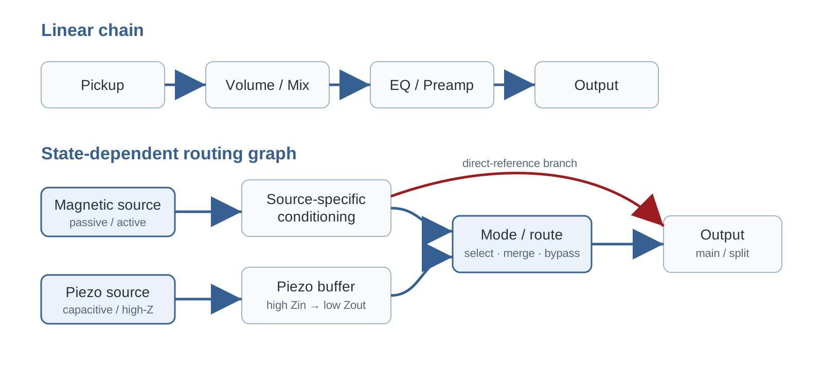
Figure 1. B06 synthesis. Source-specific conditioning, direct-reference branch와 selectable merge가 존재하면 하나의 직렬 chain보다 state-dependent graph가 더 정확한 문서화 형식이 된다.
5. Source Domains — passive magnetic, active magnetic, piezo를 분리하는 근거
Passive magnetic pickup은 pickup의 Z(f)와 외부 pot/cable/input load가 직접 결합되는 source다. 반면 EMG 35/40-series active pickup은 전원과 내부 electronics를 사용하고 공식 output impedance가 10 kΩ으로 제시된다 [5–6]. 이 둘은 같은 “magnetic pickup”이라도 downstream loading에 대한 경계조건이 다르다.
Piezo는 또 다른 경우다. TI는 piezo sensor의 높은 source impedance를 전제로 high-input-impedance JFET/CMOS front end를 다룬다 [9]. Fishman의 특정 passive piezo guidance에서는 10 MΩ에서 full response가 가장 잘 유지되고 1 MΩ에서도 사용 가능하나 bass가 다소 roll-off될 수 있다고 설명한다 [8]. 따라서 RavenForge는 source type을 단순 pickup 분류가 아니라 source Z, level, required Zin, buffering need로 기록한다.
6. ESH / Eshtronic — 현재 사양과 역사적 routing을 분리한다
현행 ESH product pages는 Stinger 계열에 Volume, Tone, Pickup Selector, Mode Selector, Esh-tronic active electronics와 Esh Custom piezo bridge가 존재함을 확인하는 데 사용할 수 있다 [2–3]. 다만 특정 모델·현수·옵션의 EMG 조합은 해당 option page에서 개별 확인해야 한다.
반면 4-state routing의 상세는 historical evidence다. 과거 리뷰와 owner reports에서는 Studio/Direct, magnetic with controls, magnetic + piezo, piezo-only로 설명되는 구현이 반복적으로 나타난다 [4,11–12]. 이 일치는 역사적 implementation의 존재 가능성을 강하게 지지하지만, 현행 Stinger II의 내부 switching topology가 동일하다는 공식 증거는 아니다.
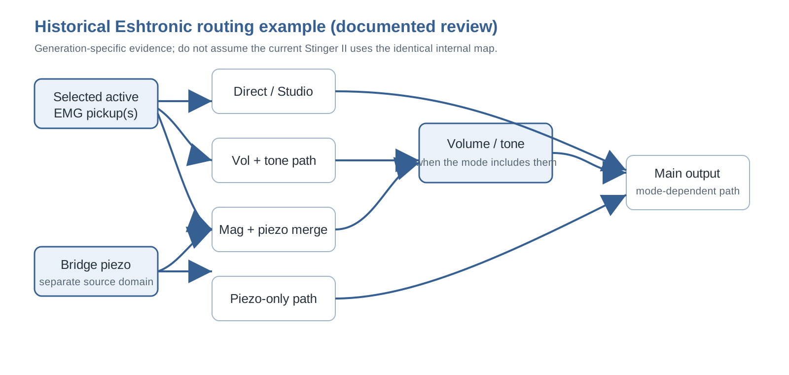
Figure 2. Historical implementation model. 현행 Eshtronic의 공식 회로도로 제시하는 것이 아니라, 문서화된 과거 state description을 graph로 재구성한 것이다.
7. Studio/Direct — “Passive”가 아니라 Direct-source Reference
EMG-equipped configuration에서 Studio/Direct를 passive라 부르는 것은 맞지 않는다. Volume/Tone 또는 후단 board를 우회하더라도 EMG pickup 내부의 active electronics와 low-Z output condition은 남는다 [5–6]. 따라서 B06은 이를 Direct-source reference로 명명한다.
Terminology boundary |
단, 과거 Eshtronic의 모든 세대가 EMG active pickup만 사용했다고 일반화해서는 안 된다. Bartolini 등 다른 source가 사용된 historical configuration은 그 source의 실제 electrical architecture를 별도로 확인해야 한다.
8. Piezo Boundary — 1 MΩ과 10 MΩ을 어떻게 읽어야 하는가
Fishman의 10 MΩ 권장은 “모든 piezo는 반드시 10 MΩ”이라는 universal rule이 아니다. 특정 passive piezo system에서 10 MΩ input이 full response를 가장 잘 보존하고 1 MΩ에서는 bass roll-off가 생길 수 있다는 manufacturer guidance다 [8]. 일반화 가능한 부분은 piezo source capacitance와 input resistance가 저역 boundary를 형성하므로 충분히 높은 Zin이 중요하다는 점이다 [9].
단순 모델에서 fc ≈ 1/(2π·Rin·Cp)로 방향성을 볼 수 있지만, B06의 5 nF/10 nF 예시는 RavenForge의 illustrative calculation일 뿐 Esh piezo의 실측 capacitance가 아니다. 실제 설계값은 sensor/bridge network를 측정한 뒤 정해야 한다.
9. Mixing과 B125 — Blend knob가 아니라 isolation architecture
EMG B125 documentation은 각 pickup input에 buffer를 두고 passive/passive, active/active, active/passive source 조합을 지원한다고 설명한다 [7]. 이는 mixing 전에 source를 isolation하는 구조가 실제 commercial implementation에 존재한다는 강한 근거다.
따라서 B06은 magnetic + piezo mixing을 단순 “50:50 blend”로 표현하지 않는다. source별 conditioning, gain, polarity/phase relation, summing node를 분리해 기록한다. 다만 B125가 모든 magnetic+piezo 조합의 정답이라는 의미는 아니며, piezo의 required Zin이 B125 input 조건과 맞는지는 별도 검토가 필요하다.
10. Control Placement — 25 kΩ 규칙을 과잉 일반화하지 않는다
EMG의 BTC-HZ/B125 시스템 문서는 low-output-impedance active control 뒤에서 25 kΩ Volume을 사용하고 기존 250/500 kΩ Volume/Tone을 사용하지 말라고 지시한다 [7]. 이는 해당 low-Z system에 대한 공식 wiring rule이다.
따라서 “active pickup에는 무조건 25 kΩ”, “250/500 kΩ을 쓰면 반드시 loading imbalance가 발생한다”라고 일반화해서는 안 된다. pot value는 source Z, circuit topology, noise objective와 제조사 권장에 따라 정해야 한다. B06의 설계 원칙은 값 자체가 아니라 buffer 전/후, mix 전/후 어디에 control이 놓이는지를 기록하는 것이다.
11. Switching Transient — state 전환도 회로 동작이다
Analog Devices의 audio-switch 자료는 charge injection, DC offset 차이, break-before-make, shunt discharge가 click/pop에 영향을 줄 수 있음을 설명한다 [10]. 이 원리는 B06의 mode-switching validation 항목을 지지한다.
하지만 이것이 현행 Eshtronic에서 특정 switch IC나 특정 anti-pop topology를 사용한다는 뜻은 아니다. ESH의 switch contact scheme은 미공개로 남겨 두고, RavenForge prototype에서는 steady-state response와 별개로 transition transient를 측정한다.
12. Split Output — 사실과 owner testimony의 경계
일부 과거 Esh/Stinger 사용자 자료에는 normal output과 direct piezo output을 함께 언급하는 사례가 있다 [11–12]. 그러나 제조사 current specification으로 충분히 고정할 1차 근거는 확보되지 않았다.
따라서 B06에서 split-output은 “ESH의 보편적 사양”이 아니라 실제 악기 설계에서 가능한 routing primitive로만 사용한다. RavenForge가 이를 채택할 경우 별도 jack, grounding, cable workflow, stage/recording 목적을 자체 설계 요구사항으로 정당화해야 한다.
13. RavenForge Routing Taxonomy — 유용한 synthesis와 한계
| Type | 정의 | 근거/용도 | 한계 |
|---|---|---|---|
| Sequential | 모든 source가 공통 chain 통과 | 기본 topology 설명 | 서로 다른 source boundary를 숨길 수 있음 |
| Direct-reference | 일부 controls/stages 우회 | ESH historical case와 reference A/B | “passive”와 혼동 위험 |
| Source-specific parallel | source별 독립 conditioning/filter | piezo/magnetic, EDDA-like branch 설명 | 부품·배선·gain matching 증가 |
| Selectable merge | state에 따라 branch 병합 | mode-based internal mixing 설명 | phase/level/transient 관리 필요 |
| Split-output | source별 독립 output | 외부 processing workflow | 사용 복잡도 증가 |
| Programmable state selector | 물리 control이 relay/logic layer의 routing state를 선택·recall | 3-pickup multi-topology, compact UI, preset recall | power·firmware·failsafe·service dependency를 함께 설계해야 함 |
이 분류는 표준 전자공학 taxonomy가 아니라 RavenForge documentation tool이다. 목적은 우열을 매기는 것이 아니라 schematic과 user state를 추적 가능한 언어로 만드는 것이다.
13A. McGrath — programmable selector가 routing state machine이 되는 사례
McGrath가 2026년 6월 공개한 12-Way Rotary Selector는 3픽업을 12개의 고정 mechanical contact 조합으로 직접 연결하는 로터리가 아니라, 전원이 필요한 control board와 relay switching으로 routing state를 선택한다 [14]. 기본 map은 각 픽업 단독, 모든 2픽업 parallel/series 조합, Bridge+Middle series를 Neck과 parallel로 병합한 state, All Parallel, All Series를 포함한다.
여기서 중요한 것은 state 수 자체보다 physical control과 electrical topology가 분리되어 있다는 점이다. Push/long-press로 favorite 저장·호출과 previous-state 복귀가 가능하고, 2026년 8월 공개된 companion app에서는 12개보다 적은 active position을 쓰거나 총 14개의 tonal possibility를 원하는 position에 재배치할 수 있다 [14–15]. 즉 knob position은 더 이상 하나의 납땜된 contact map과 1:1로 고정되지 않는다.
Fret Nation의 판매 사양은 pickup lead용 screw-down terminal, 기존 9 V/18 V 전원 사용, triple-tap reset, 전원 상실 시 All Parallel fallback을 명시한다 [16]. B06의 관점에서 이는 programmable switching을 채택할 때 state map, recall behavior, reset, power-loss state와 service access까지 회로 사양의 일부로 기록해야 한다는 실제 사례다. McGrath의 구현을 그대로 답습할 필요는 없지만, EMBLA 같은 3-pickup option에서는 mechanical selector만 비교할 것이 아니라 이 architecture class도 후보로 포함할 가치가 있다.
14. Correction Required — 기존 초안에서 수정할 표현
| 기존 표현/위험 | 수정 |
|---|---|
| “현행 Eshtronic의 4-state routing은 과거와 동일하다” | 삭제. Historical implementation과 current specification을 분리. |
| “Studio mode = passive” | EMG-equipped configuration에서는 Direct-source reference로 수정. |
| “Piezo는 10 MΩ 이상이 필요하다” | “High Zin이 중요하며 10 MΩ은 특정 Fishman example의 권장값”으로 수정. |
| “Active pickup은 25 kΩ control을 써야 한다” | 제품별 topology에 따라 다름. 25 kΩ은 EMG low-Z system 문맥으로 한정. |
| “1 MΩ이면 수백 Hz에서 -3 dB” 같은 고정 예상치 | 삭제. Cp와 network를 측정하지 않은 상태에서 예측하지 않음. |
| “Split piezo output은 Stinger II의 일반 사양” | 삭제. owner testimony 기반 historical/variant possibility로 한정. |
| 관련 없는 Stenback 자료 | B06 evidence set에서 제외. |
15. RavenForge 모델 적용 — 사실이 아니라 설계 제안으로 명시한다
ASKR
ASKR의 active EMG source + Tone Capsule 구성에서는 EQ bypass를 passive라 부르지 않는다. Direct-source reference vs EQ path를 비교 가능한 두 state로 설계하는 것이 합리적이다. 다만 실제 level matching, switching transient와 battery-failure behavior는 prototype에서 검증해야 한다.
EMBLA
Passive pickup + onboard preamp 구조에서는 pickup interaction을 preamp 앞에서 보존할지, pickup별 isolation 뒤에 blend할지를 먼저 결정한다. 3-pickup option을 고려한다면 selector logic, branch count, gain/polarity consistency, service access를 specification에 포함한다. McGrath형 programmable relay selector는 유력한 비교군이지만, 실제 채택 전에는 필요한 state subset, cavity/PCB 공간, 9/18 V power budget, power-loss fallback과 앱 의존성을 별도로 평가한다 [14–16].
EDDA
2 Volume / 2 Filter 구상은 per-source processing before merge라는 source-specific parallel architecture로 정리할 수 있다. 이는 Alembic/Wal을 복제했다는 사실 주장이 아니라 RavenForge의 설계 방향이다. 실제 filter law, interaction과 summing loss는 후속 회로/측정 단계에서 결정한다.
16. Prototype Measurement Protocol — 검증해야 할 것
| 항목 | 측정 | 목적 |
|---|---|---|
| Source / input boundary | Zin sweep, source Z(f), piezo capacitance/equivalent response | branch별 conditioning 적합성 확인 |
| State response | mode별 gain/frequency response | Direct/controlled/merged state 차이 정량화 |
| Level matching | magnetic/piezo/merged output RMS & peak | mode jump와 summing balance 확인 |
| Switch transient | oscilloscope/audio capture의 click/pop peak와 duration | state transition quality 검증 |
| Noise | mode별 output noise, bandwidth 명시 | buffer/routing penalty 확인 |
| Power failure | battery sag/removal state | 어떤 branch가 mute/fail/survive하는지 기록 |
| State-map integrity | 각 physical position, favorite/previous recall, reset, power-loss state와 app remap 대조 | 표시 state와 실제 routing의 일치 검증 |
| Serviceability | test node access와 fault isolation | 실제 유지보수 가능성 검증 |
측정 전에는 “Studio mode에서 몇 dB 상승”, “1 MΩ에서 정확히 어느 주파수부터 roll-off” 같은 effect size를 예측값처럼 기록하지 않는다.
17. 현재 결론 — 부품 목록보다 boundary와 state를 먼저 기록한다
Verified B06 conclusion |
심층 검증 후에도 B06의 방향은 유지된다. 다만 설계 언어와 제품 사실을 더 엄격하게 분리해야 한다. ESH에서 얻는 핵심은 “4-way switch를 그대로 복제하자”가 아니라, source마다 필요한 boundary를 분리하고, reference state를 명시하고, merge/split을 의도적으로 설계하며, 사용자가 현재 state를 이해할 수 있게 하자는 것이다. 여기에 McGrath 사례는 selector 자체도 고정 contact map이 아니라 relay/logic 위의 programmable interface가 될 수 있음을 보여준다 [14–16]. 따라서 B06의 state-dependent signal graph는 역사적 특수 사례를 설명하는 언어가 아니라 현행 상용 architecture까지 포괄하는 specification framework로 확장된다. 이 프레임을 기준으로 A07에서는 supply voltage와 headroom을 독립 변수로 이어서 검증한다.
References
[1] RavenForge. “A06 — Onboard Preamp Architecture.” Signal & Transduction Research Log, 2026-09-18.
[2] Esh Basses. “Stinger II.” Current product page. Controls/electronics include Volume, Tone, Pickup Selector, Mode Selector, Esh-tronic active electronics and Esh Custom piezo bridge. https://www.esh-bass.com/products/32474-stinger-ii
[3] Esh Basses. Current Stinger-family product/options pages. EMG 35/40-series pickup assignments vary by model/string-count option. https://www.esh-bass.com/
[4] Musiccraft24. “The Dark Side of Esh” / historical Stinger review. Documents a four-state Eshtronic implementation and Direct/Studio concept; treated as historical, generation-specific evidence. https://www.musiccraft24.de/index.php?eID=dumpFile&f=8219&t=f&token=d7ee41d92e4bb2fabca7bf3e35be4ba8725803c4
[5] EMG Pickups. “35 Bass Pickups” specification sheet. Output impedance 10 kΩ for the listed 35-series active models. https://www.emgpickups.com/pub/media/Mageants/3/5/35_bass_0230-0127rb.pdf
[6] EMG Pickups. “40 Bass Pickups” specification sheet. Output impedance 10 kΩ for the listed 40-series active models. https://www.emgpickups.com/pub/media/Mageants/4/0/40_bass_0230-0128rb.pdf
[7] EMG Pickups. B125 Active Balance / BTC-HZ system documentation. Per-input buffering, active/passive source mixing and low-Z downstream control guidance. https://www.emgpickups.com/pub/media/Mageants/h/z/hz_btchz_system_0230-0204re.pdf
[8] Fishman. V-200 / passive piezo installation guidance: best response into 10 MΩ; usable at 1 MΩ with some bass roll-off. Legacy manufacturer guidance; archived/mirrored copies may be required for access.
[9] Texas Instruments. “Signal Conditioning Piezoelectric Sensors,” SLOA033A. High source impedance and high-input-impedance JFET/CMOS front-end guidance. https://www.ti.com/lit/an/sloa033a/sloa033a.pdf
[10] Analog Devices. “Selecting the Right CMOS Analog Switch.” Audio click/pop, charge injection, break-before-make and discharge considerations. https://www.analog.com/en/resources/design-notes/selecting-the-right-cmos-analog-switch.html
[11] Bassic.de. “Eshtronic gegen passive Elektronik tauschen?” and related Esh discussions. Owner/community evidence for historical Studio-mode philosophy; secondary evidence only. https://www.bassic.de/threads/eshtronic-gegen-passive-elektronik-tauschen.14810494/
[12] TalkBass. “ESH bass club” and related owner discussions. Repeated owner descriptions of piezo-only / piezo+magnetic / magnetic+controls / Studio routing; secondary evidence only. https://www.talkbass.com/threads/esh-bass-club.697883/page-3
[13] RavenForge. “B03 — Passive Tonal Architecture.” Signal & Transduction Research Log, 2026-09-17.
[14] McGrath Guitars. “McGrath 12 Way Rotary Pickup Selector.” 2026-06-28. Relay-switched three-pickup selector; twelve factory routing states, favorite/previous recall and All-Parallel power-failure fallback. https://mcgrathguitars.com/blogs/news/12-way-rotary-selector
[15] McGrath Guitars. “We made an app!” 2026-08-01. Companion app supports fewer than twelve active positions and assignment of fourteen tonal possibilities to switch positions. https://mcgrathguitars.com/blogs/news/we-made-an-app
[16] Fret Nation. “McGrath Guitars 12-Way Rotary Selector Switch.” Product page. Screw-down pickup terminals, 9 V/18 V supply, recall/reset behavior and All-Parallel failsafe. https://fretnation.com/products/mcgrath-guitars-12-way-rotary-selector-switch
[17] ZUTA Group. “ZUTA CORE MANUAL.” Official installation manual. https://cdn.shopify.com/s/files/1/0318/3987/9307/files/ZUTA_CORE_MANUAL.pdf?v=1760376558
[18] ZUTA Group. “ZUTA LUXE.” Official product page. https://zutagroup.com/products/zuta-luxe
[19] Fender Musical Instruments Corp. “ERIC CLAPTON STRATOCASTER UPGRADE 0117602” Service Diagram. https://www.fmicassets.com/Damroot/Original/10002/011-7602A_SISD.pdf
[20] Fender. “Iconic Mods: Eric Clapton’s ‘Blackie’ Stratocaster.” https://www.fender.com/articles/behind-the-scenes/iconic-mods-eric-claptons-blackie
[21] Wacker, D. “The Fender Eric Clapton Active Mid-Boost.” Premier Guitar, 2010. https://www.premierguitar.com/diy/mod-garage/clapton-mid-boost
[22] Aion FX. “Elite Boost/Preamp — Fender MDX/Clapton Mid-Boost.” Circuit reconstruction/build documentation. https://aionfx.com/project/elite-boost-preamp/
[23] EMG Pickups. “SPC / RPC Installation Information 0230-0160rB.” https://www.emgpickups.com/pub/media/Mageants/s/p/spc_rpc_0230-0106rb.pdf
[24] Wal Basses. “Components — Preamp.” Official manufacturer description. https://walbasses.co.uk/components/
[25] East UK / John East. “UNI-PRE 5 Knob User Manual.” https://www.east-uk.com/2025/11/28/uni-pre-5-knob-user-manual/
[26] Rhodes, O. J.; Peavey Electronics Corp. US4164163A, “Electric guitar circuitry.” https://patents.google.com/patent/US4164163A/en
[27] Demeter Amplification. “MB-2 Midboost/Fat Control.” https://demeteramps.com/product/mb-2-midboost-fat-control/
[28] Demeter Amplification. “MB-2B Midboost/Fat Control User’s Guide.” https://demeteramps.com/manuals/mb2busersguide.pdf
[29] Peavey Electronics. “T-60/T-40 Owner’s Manual.” Original manual / archival reproduction; patent linkage US4164163A.