RAVENFORGE / SIGNAL & TRANSDUCTION RESEARCH LOG — A04
RAVENFORGE
Signal & Transduction Research Log
A04 — Electrical Loading of Passive Pickups
픽업 자체의 Z(f)에서 실제 악기 출력까지 — 저항성·용량성 부하와 control topology가 loaded response를 바꾸는 방식
문서 목적 A03에서 확립한 passive pickup의 source + Zpu(f) 모델을 실제 악기 경계조건으로 확장한다. volume/tone controls, cable capacitance, downstream input resistance/capacitance를 하나의 loaded system으로 다루고, 250 kΩ / 500 kΩ / 1 MΩ 같은 관행을 고정된 “tone recipe”가 아니라 측정 가능한 damping·resonance 조건으로 재정의한다. A04는 passive loading까지 다루며 active buffer의 격리 메커니즘은 A05로 넘긴다. |
Code | A04 |
Focus | external load · volume/tone topology · cable capacitance · input impedance · loaded transfer response |
Evidence | peer-reviewed AES cable study · JAES pickup modeling · circuit analysis · technical monographs · component datasheets |
RavenForge link | A03 intrinsic pickup Z(f) → A04 loaded response → C02 measurement → A05 buffer isolation |
Downstream logs | C02 / A05 |
Status | core circuit model verified · model-specific values pending C02 validation |
1. 연구 질문 — 같은 pickup이 왜 하나의 고정된 “tone”을 갖지 않는가
A03은 passive magnetic pickup을 이상적인 tone source가 아니라 induced source와 frequency-dependent terminal impedance Zpu(f)의 결합으로 정리했다. 그러나 실제 악기에서 pickup output node에는 volume pot, tone branch, cable, 다음 장치의 input이 동시에 연결된다. 따라서 실사용 frequency response는 pickup 단품의 고유값이 아니라 pickup과 외부 boundary condition의 결합 결과다.
Paiva & Penttinen의 AES 131st Convention 논문은 실제 instrument cable을 측정·모델링하여 cable capacitance가 magnetic-pickup system의 frequency response를 바꾸며, 조사한 cable들 사이에서 resonant-frequency 차이가 최대 1.4 kHz였다고 보고했다. 이 1.4 kHz는 보편적 cable 효과의 상한이 아니라 그 연구의 측정 cable set과 pickup/load 조건에서 나온 최대 차이다 [1,3].
핵심 관점 Pot value, cable length, “high-Z input”은 부품 이름이 아니라 boundary-condition metadata다. RavenForge는 nominal label보다 실제 R, C, wiring state와 downstream interface를 기록한다. |
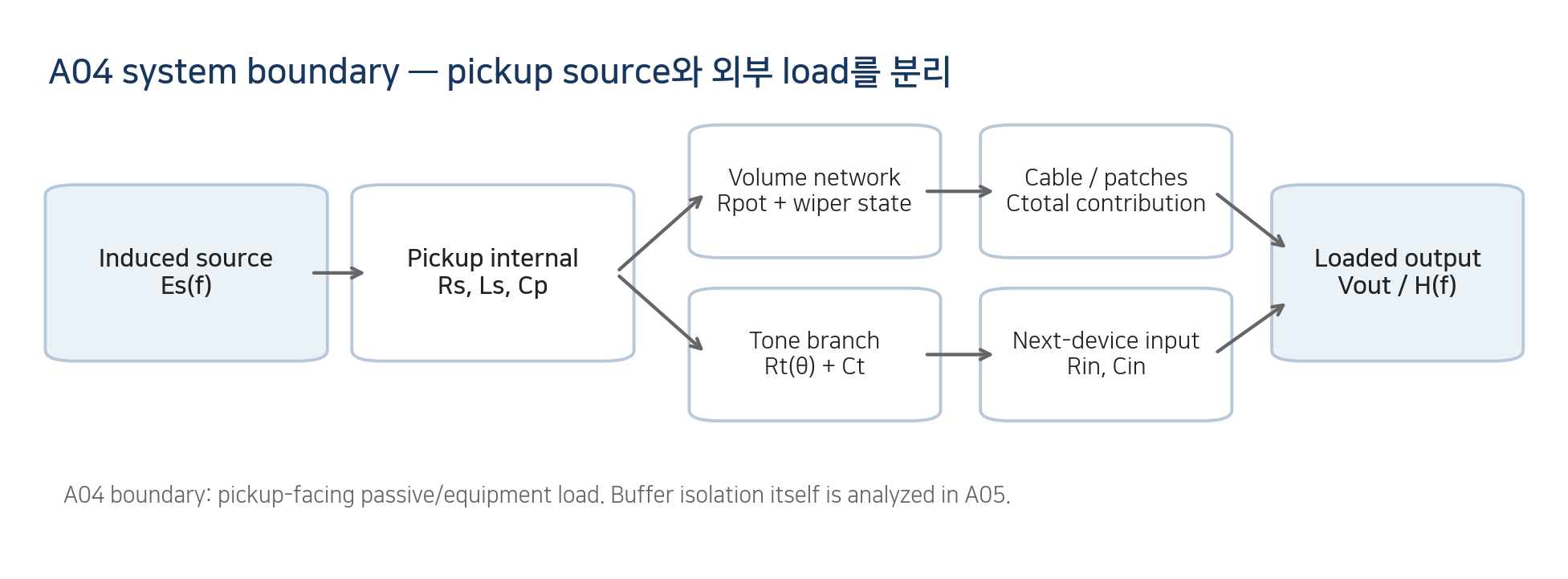
Figure 1. A03 pickup model과 A04 external loading의 system boundary.
Engineering schematic. Passive/equipment load까지만 A04 범위이며 buffer isolation은 A05로 분리한다.
2. Reference circuit — 가장 단순한 full-volume case부터 정의한다
A04의 reference case에서는 tone branch를 생략하고 volume을 full로 둔다. induced source Es가 coil series impedance Zs=Rs+sLs를 통해 output node를 구동하고, 그 node에는 pickup equivalent winding capacitance Cp와 external load가 shunt된다. external load를 Rload와 Cext로 단순화할 수 있을 때 C_T=Cp+Cext, R_L=Rpot∥Rin으로 둘 수 있다. 이 합산은 모든 capacitance가 같은 electrical node에서 ground로 보이는 경우에만 유효하다.
H(s) = Vout/Es = 1 / [ 1 + (Rs + sL) (1/RL + sCT) ]
= 1 / [ 1 + Rs/RL + s(L/RL + Rs·CT) + s²L·CT ]
이 식은 “pickup 자체의 resonance”가 아니라 specified external load를 포함한 output-voltage transfer다. tone control, partial-volume wiper, multiple pickups가 들어오면 scalar R_L/C_T로 축약하지 말고 실제 topology를 nodal analysis 또는 circuit simulation으로 계산해야 한다.
수학적 주의 이 단순 2차 모델에서 resonant transfer peak가 존재한다면 ωpeak²=[2a0a2−a1²]/(2a2²), a0=1+Rs/RL, a1=L/RL+RsCT, a2=LCT. 따라서 load resistance는 peak height/Q뿐 아니라 peak position에도 영향을 줄 수 있다. 1/(2π√(LCT))는 high-Rload·low-loss limit의 근사다. |
3. Resistive loading — 250 kΩ / 500 kΩ / 1 MΩ은 damping 조건이다
full-volume 상태에서도 volume pot의 end-to-end resistance는 pickup node에서 ground로 연결된 resistive load로 남고, downstream input resistance와 병렬 결합한다. 동일 pickup·capacitance 조건에서 더 큰 R_L은 일반적으로 damping을 줄여 resonant peak를 더 높게 유지한다. 그러나 “500 kΩ은 항상 brighter”라는 문장은 조건이 빠져 있다. peak 위치·높이와 최종 지각은 pickup L/R/C, cable/input C, tone branch, volume state와 함께 결정된다.
또한 nominal pot 값은 실제 값과 같지 않을 수 있다. 예를 들어 Bourns Model 82 guitar potentiometer는 standard resistance tolerance ±10%, Model 95는 ±20%를 명시한다 [6,7]. 따라서 prototype log에는 “500 kΩ”만 쓰지 않고 measured end-to-end resistance와 taper/position을 기록하는 편이 재현성에 유리하다.
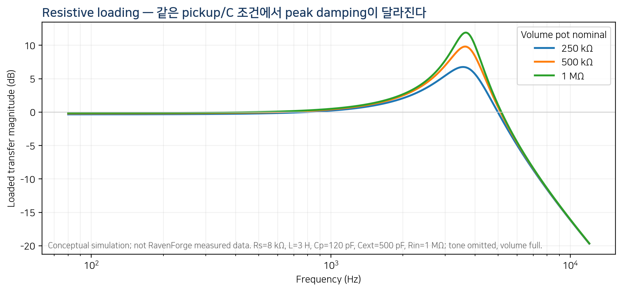
Figure 2. 250 kΩ / 500 kΩ / 1 MΩ resistive loading의 개념 비교.
계산 예시이며 RavenForge pickup 실측값이 아니다. legend의 pot 값과 fixed Rin=1 MΩ이 병렬로 결합한다.
4. Capacitive loading — cable은 길이보다 total capacitance로 관리한다
instrument cable은 distributed structure이지만 typical instrument-cable length와 audio band에서는 electrical length가 매우 짧아 lumped shunt capacitance 근사가 실용적이다. 같은 cable construction이라면 total capacitance는 대체로 capacitance-per-length × length로 증가하지만, assembled cable에서는 connectors, patch wiring, device input capacitance가 추가된다. 따라서 “3 m”보다 measured total pF가 더 직접적인 electrical descriptor다.
Paiva & Penttinen은 cable inductance와 series/parallel resistance의 영향은 그들의 측정·시뮬레이션 조건에서 작고 capacitance가 지배적이라고 보고했다 [1]. 이는 “low-capacitance cable이 무조건 superior”라는 뜻이 아니다. capacitance를 낮추면 같은 pickup에서 resonance가 위로 이동하는 경향이 있으므로, low-C는 voicing 선택이지 보편적 품질 점수가 아니다. Canare GS-6의 공식 nominal capacitance는 160 pF/m처럼 cable마다 명시값이 다르다 [8].
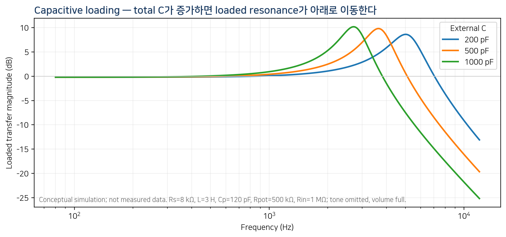
Figure 3. External capacitance가 loaded response에 미치는 개념적 영향.
동일 pickup/load에서 Cext만 변경한 계산 예시. pF 값은 illustrative test points이며 cable 품질 등급이 아니다.
5. Input impedance — 1 MΩ도 ‘unloaded’가 아니다
amp, pedal, DI, interface input은 finite resistance와 parasitic/input capacitance를 갖는다. input resistance는 pickup node를 resistively load하고 input capacitance는 cable C와 같은 node에서 합산될 수 있다. 따라서 “1 MΩ input”은 high impedance일 수는 있어도 무한대가 아니며, no-cable bench test도 probe/fixture capacitance에서 자유롭지 않다.
RavenForge에서는 “unloaded” 대신 specified high-impedance / specified-capacitance fixture를 사용한다. 실제 제품 비교에서도 input label만 믿기보다 가능한 경우 Rin, Cin, cable/patch configuration을 함께 기록한다. buffer가 downstream cable capacitance를 pickup에서 격리하는 원리는 A05에서 정식으로 다룬다.
6. Volume control — knob를 내리면 level과 topology가 함께 변한다
conventional passive volume pot에서 wiper가 full 위치를 벗어나면 input-to-wiper 저항 Ra와 wiper-to-ground 저항 Rb가 생긴다. downstream cable/input은 wiper에 연결되므로 Rb와 병렬 또는 복합 network를 만들고, Ra는 pickup과 output 사이의 series path가 된다. 그 결과 attenuation뿐 아니라 wiper source impedance와 cable capacitance의 결합으로 frequency response도 변할 수 있다.
audio/log taper는 resistance-versus-rotation law를 정하는 것이지 회로 topology를 바꾸는 것이 아니다. treble-bleed network는 이 state-dependent loss를 보상하기 위한 별도 frequency-dependent path이며 universal cure가 아니다. “volume down = same tone, lower level”은 passive high-impedance system에서는 일반적으로 성립하지 않는다.
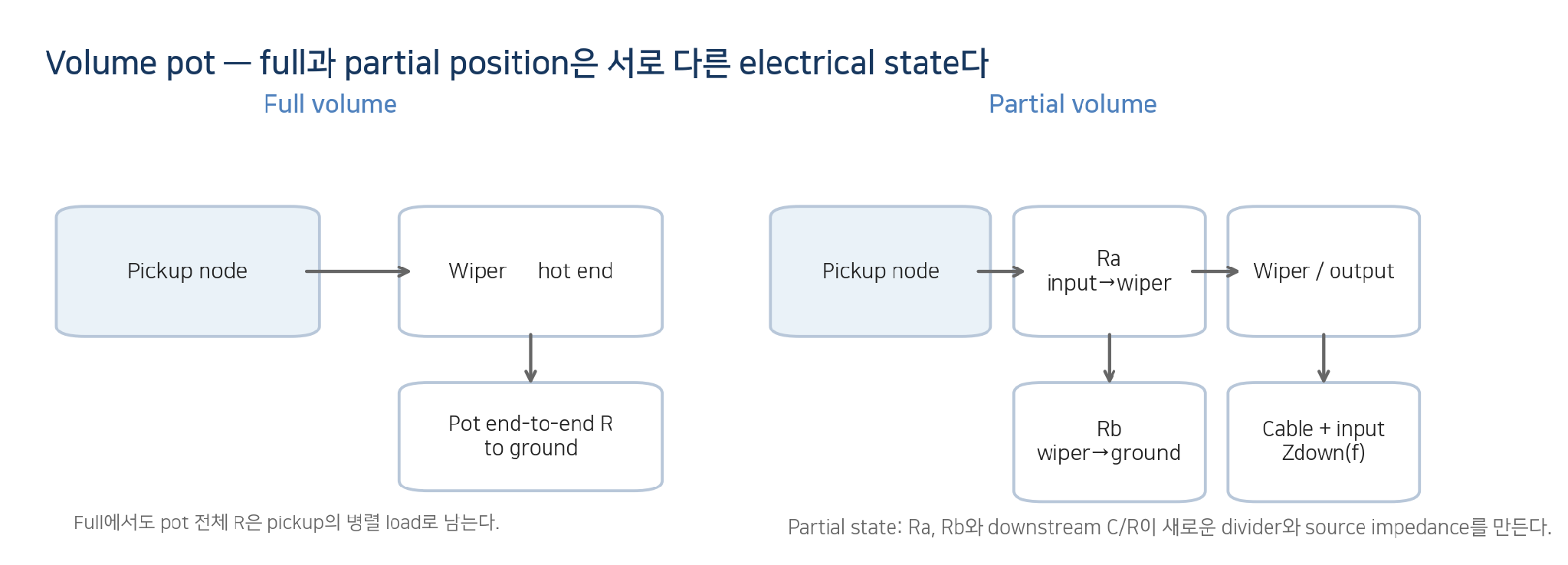
Figure 4. Full-volume과 partial-volume에서 volume pot이 만드는 서로 다른 load state.
Simplified topology. 실제 response는 tone branch와 downstream input까지 포함해 계산한다.
7. Tone control — ‘10’에서도 standard tone branch는 완전히 사라지지 않는다
가장 흔한 passive tone control은 variable resistance Rt(θ)와 capacitor Ct가 series branch로 ground에 연결되는 형태다. branch impedance는 Ztone=Rt(θ)+1/(sCt)로 볼 수 있지만, 전체 response는 pickup·volume·cable·input network와 함께 계산해야 한다. standard pot에서 tone이 fully open이어도 Rt가 유한하므로 branch는 약하게 남는다. 반면 no-load tone pot은 end position에서 tone branch를 물리적으로 disconnect하도록 설계된 별도 topology다.
22 nF, 47 nF 같은 capacitor value는 특정 pickup type의 정답이 아니다. 같은 capacitor라도 pickup inductance와 load resistance가 다르면 resonance/rolloff가 달라진다. ‘modern’과 ‘50s’ wiring도 tone branch가 volume pot의 어느 node에 연결되는지가 다르므로 volume을 움직일 때 interaction이 달라지는 topology 문제로 다뤄야지, 한 쪽이 보편적으로 더 “좋다”고 서술하면 안 된다.
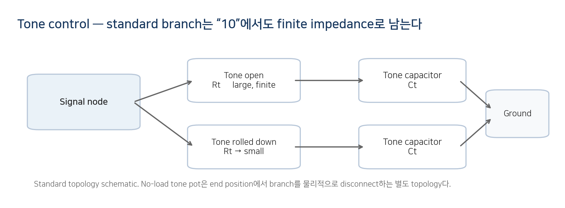
Figure 5. Standard passive tone branch의 knob-state 개념도.
Rt와 Ct의 branch는 전체 guitar network의 일부다. no-load pot은 별도 disconnect topology로 취급한다.
8. Multiple pickups — spatial mix와 electrical interaction을 분리한다
두 passive pickup을 동시에 선택하면 A02에서 다룬 spatial sampling/phase가 합쳐지는 동시에 두 source impedance와 control network도 서로 연결된다. 병렬 조합은 단순한 “두 전압의 산술합”이 아니며, series/parallel switching과 independent V/V wiring에서는 각 pickup이 다른 pickup과 pot network의 load가 될 수 있다. selector state별 loaded transfer를 별도 state로 기록해야 한다.
9. 근거 매트릭스 — A04에서 어디까지 주장할 수 있는가
주장 | 판정 | A04 처리 |
500 kΩ pot은 250 kΩ보다 항상 밝다 | 조건부 | 동일 topology·pickup·C에서 더 큰 R은 보통 damping을 줄이지만 “brightness”와 peak 위치는 전체 network에 의존. |
1 MΩ이 항상 가장 좋고 open하다 | 근거 없음 / 가치판단 | 더 큰 R은 loading을 줄일 수 있으나 최적값은 target response와 noise/interface 조건의 문제. |
250 kΩ=single coil, 500 kΩ=humbucker | 관행이지 물리법칙 아님 | pickup type label만으로 load를 결정하지 않는다. |
pot value가 pickup intrinsic R/L/C를 바꾼다 | 수정 필요 | coil 자체 parameter가 아니라 loaded transfer condition을 바꾼다. |
Rload는 Q만 바꾸고 peak frequency는 절대 안 바꾼다 | 틀림 | 단순 2차 transfer에서도 finite damping은 peak position에 영향을 줄 수 있다. |
긴 cable은 무조건 tone이 나빠진다 | 틀림 | 같은 cable이면 C가 늘 수 있지만 “나쁨”은 가치판단; total C를 측정해야 한다. |
low-capacitance cable은 무조건 superior | 근거 없음 | resonance를 위로 이동시키는 voicing choice. |
1 MΩ input은 사실상 unloaded다 | 수정 필요 | finite R이며 Cin/fixture C도 존재. |
volume knob는 level만 바꾼다 | 틀림 | partial wiper state가 source impedance와 downstream C interaction을 바꾼다. |
tone 10이면 tone circuit이 완전히 사라진다 | topology-dependent | standard pot은 finite branch; no-load pot은 end position에서 disconnect 가능. |
22 nF/47 nF에는 정답 pickup type이 있다 | 근거 없음 | L, Rload, topology와 함께 결정. |
두 pickup parallel은 단순 신호 합이다 | 수정 필요 | 각 source impedance와 controls가 서로 loading. |
buffer 뒤 cable C도 passive pickup resonance를 똑같이 바꾼다 | A05로 이동 / 일반적으로 틀림 | 충분한 buffer isolation이면 downstream C가 pickup node에서 격리됨. |
10. C02 — Pickup Loading Measurement protocol
A04의 문헌·회로 결론은 실제 RavenForge pickup/load 조합에서 effect size를 측정해야 specification이 된다. C02에서는 pickup baseline과 excitation을 고정하고 Rload/Cload를 controlled substitution하여 Hloaded(f)를 비교한다. 임의의 “유의미” threshold를 미리 만들지 않고 repeatability와 measurement uncertainty를 먼저 추정한 뒤, 목표 voicing과 effect size를 비교한다.
Stage | Record / condition | Decision |
1. Baseline | Pickup mounting/excitation, temperature, wiring state 고정 | reference state lock |
2. Component metrology | actual pot end-to-end R, taper position, cable/fixture total C | nominal vs actual 분리 |
3. R-load matrix | precision resistor 또는 measured pot로 Rload 조건 설정 | resistive effect isolation |
4. C-load matrix | known C / measured cable / fixture Cin으로 Cload 설정 | capacitive effect isolation |
5. Transfer sweep | 동일 excitation에서 magnitude + phase Hloaded(f) | frequency-dependent effect |
6. Feature extraction | fpeak, peak gain, bandwidth/Q when valid | do not force Q if no clear peak |
7–8. Repeatability + archive | reconnect / reposition / repeat; estimate uncertainty; retain raw complex data + exact topology | effect > measurement noise? / traceable design rule |
각 상태에서 measured pot R, total C, fixture Rin/Cin, wiring state를 기록한다. peak가 충분히 정의되는 경우 fpeak, peak gain, bandwidth/Q를 추출하고, 그렇지 않으면 전체 complex H(f)와 residual을 보존한다.
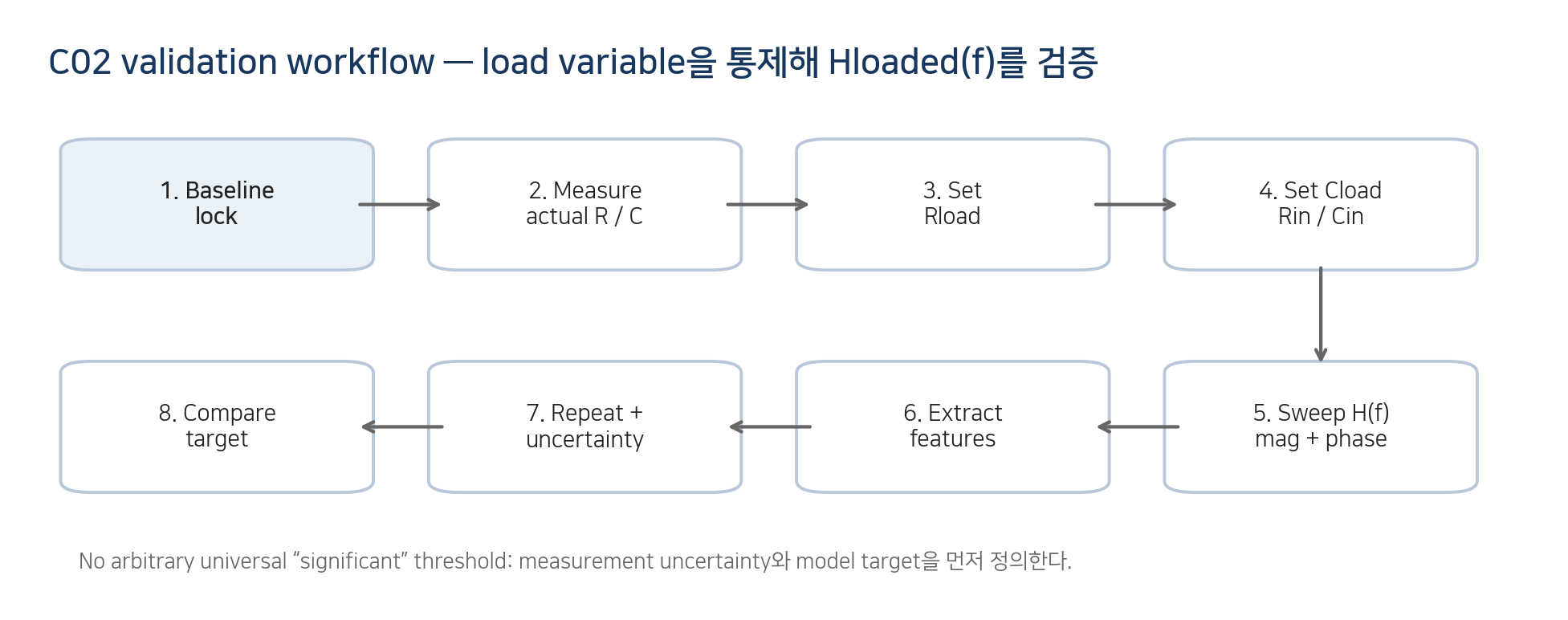
Figure 6. C02로 이어지는 RavenForge loaded-response validation workflow.
Engineering validation loop. effect-size threshold는 측정 불확도와 model target보다 먼저 고정하지 않는다.
11. RavenForge 적용 — 부품 관행이 아니라 target response에서 load를 역산한다
EDDA의 passive baseline은 “빈티지이므로 250 kΩ” 같은 recipe를 먼저 고정하지 않는다. pickup Z(f), 목표 loaded response, reference cable/input을 정의한 뒤 pot/capacitor topology를 선택한다. heritage는 역사적 nominal part value의 복제가 아니라 당시 system behavior 중 무엇을 유지할 것인지의 문제다.
EMBLA/ASKR가 passive pickup 뒤에 onboard buffer/preamp를 사용한다면 pickup이 직접 보는 input condition까지는 A04 metadata에 포함할 수 있지만, buffer output impedance와 downstream cable isolation은 A05의 architecture problem으로 분리한다. 현재 active EMG/Fishman architecture 자체는 A04의 traditional passive loading 모델로 직접 rank하지 않는다.
12. 현재 결론 — passive pickup의 output은 pickup + load의 system property다
A04의 핵심은 250 kΩ, 500 kΩ, 1 MΩ, cable length, “high-Z” 같은 label을 tone adjective로 쓰지 않는 것이다. reference topology에서는 resistive load가 damping과 peak를, capacitive load가 inductance와 함께 resonance 위치를 크게 좌우한다. partial volume, tone network, multiple pickups에서는 topology가 바뀌므로 실제 wiring state를 모델·측정해야 한다.
현재 설계 입장 RavenForge specification rule: pickup model + wiring state + measured pot resistance/taper position + total external capacitance + destination input condition → loaded-response target → C02 validation. Nominal component categories are implementation choices, not the target. |
13. 다음 연구 — C01 / C02 / A05로 넘기는 것
Code | Research question | A04에서 넘기는 변수 |
C01 | Pickup Position FFT Mapping | A02 spatial-sampling model의 실측 검증 |
C02 | Pickup Loading Measurement | A04 R/C load matrix와 Hloaded(f) 검증 |
A05 | Active Buffers and Input Impedance | pickup-facing Zin, low-Z output, cable isolation |
참고문헌
[1] Cauduro Dias De Paiva, R.; Penttinen, H. “Cable Matters: Instrument Cables Affect the Frequency Response of Electric Guitars.” 131st Convention of the Audio Engineering Society, Paper 8466, pp. 1–10 (2011). Aalto research portal classifies the conference publication as scientific / peer-review.
[2] Paiva, R. C. D.; Pakarinen, J.; Välimäki, V. “Acoustics and Modeling of Pickups.” Journal of the Audio Engineering Society 60(10), 768–782 (2012).
[3] Paiva, R. C. D. Circuit Modeling Studies Related to Guitars and Audio Processing. Aalto University doctoral dissertation (2013). Includes Publication II: Paiva & Penttinen (2011). ISBN 978-952-60-5388-2.
[4] Lemme, H. Electric Guitar: Sound Secrets and Technology. Elektor International Media, 2012. Technical monograph; not treated as peer-reviewed journal evidence.
[5] Lemme, H. E. W. “The Secrets of Electric Guitar Pickups.” Technical article / measurement notes, BuildYourGuitar resource; accessed 2026-09. Used for circuit/measurement practice, not as peer-reviewed evidence.
[6] Bourns. Model 82 Vintage Guitar Potentiometer product data: 250 kΩ / 500 kΩ range, standard resistance tolerance ±10%. Official manufacturer datasheet/product page.
[7] Bourns. Model 95 Premium Guitar Potentiometer datasheet: 25 kΩ, 50 kΩ, 250 kΩ, 300 kΩ, 500 kΩ values; total resistance tolerance ±20%. Official manufacturer datasheet.
[8] Canare. GS-6 Guitar / Instrument Cable official specifications: nominal capacitance 160 pF/m. Used only as an example of manufacturer-declared capacitance-per-length, not a universal cable value.
[R1] RavenForge / Signal & Transduction Research Log A03. “Magnetic Pickups as RLC Systems.” Figure-corrected revision, 2026.09.09.
[R2] RavenForge / Signal & Transduction Research Log A02. “Pickup Position and Harmonic Sampling.” Verified revision, 2026.09.06.
[R3] RavenForge / Design Methodology Research Log B02. “Voicing Before Specification.” 2026.09.08.
출처 상태 및 해석 범위 [1]은 Aalto 연구포털에서 peer-reviewed scientific conference publication으로 분류된 AES Convention paper다. [2]는 JAES peer-reviewed journal article, [3]은 Aalto doctoral dissertation이다. Lemme/Zollner류 자료는 악기전자 기술문헌/monograph로 사용하되 peer-reviewed evidence와 구분한다. Bourns/Canare 자료는 component specification 확인용이다. RavenForge의 reference transfer equation, Evidence Matrix와 C02 protocol은 이 자료를 악기 R&D에 적용한 engineering framework이며 prototype 실측 전에는 model-specific performance claim이 아니다. |
Working research document · 2026.09.10