RAVENFORGE / SIGNAL & TRANSDUCTION RESEARCH LOG — A04
RAVENFORGE
Signal & Transduction Research Log
A04 — Electrical Loading of Passive Pickups
From pickup Z(f) to the instrument output — how resistive/capacitive loading and control topology shape the loaded response
Document purpose Extend the passive-pickup source + Zpu(f) model established in A03 to real instrument boundary conditions. Volume/tone controls, cable capacitance, and downstream input resistance/capacitance are treated as one loaded system. Conventional values such as 250 kΩ / 500 kΩ / 1 MΩ are reframed as measurable damping and resonance conditions rather than fixed tone recipes. A04 ends at passive loading; active-buffer isolation is deferred to A05. |
Code | A04 |
Focus | external load · volume/tone topology · cable capacitance · input impedance · loaded transfer response |
Evidence | peer-reviewed AES cable study · JAES pickup modeling · circuit analysis · technical monographs · component datasheets |
RavenForge link | A03 intrinsic pickup Z(f) → A04 loaded response → C02 measurement → A05 buffer isolation |
Downstream logs | C02 / A05 |
Status | core circuit model verified · model-specific values pending C02 validation |
1. Research question — why does the same pickup not have one fixed “tone”?
A03 described a passive magnetic pickup not as an ideal tone source, but as an induced source combined with a frequency-dependent terminal impedance Zpu(f). In a real instrument, however, the pickup output node is simultaneously connected to the volume pot, tone branch, cable, and the input of the next device. The in-use frequency response is therefore a property of the pickup plus its electrical boundary conditions, not of the pickup alone.
Paiva & Penttinen’s AES 131st Convention paper measured and modeled instrument cables and reported that cable capacitance changes the frequency response of a magnetic-pickup system; among the measured cables, the largest resonant-frequency difference was 1.4 kHz. That 1.4 kHz figure is not a universal upper bound: it belongs to the cable set and pickup/load conditions used in that study [1,3].
Core view Pot value, cable length, and “high-Z input” are boundary-condition metadata, not tone labels. RavenForge records actual R, C, wiring state, and downstream interface instead of relying on nominal categories. |
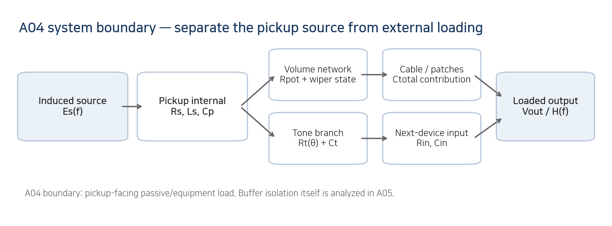
Figure 1. System boundary between the A03 pickup model and A04 external loading.
Engineering schematic. A04 ends at passive/equipment loading; buffer isolation is handled in A05.
2. Reference circuit — define the simplest full-volume case first
For the A04 reference case, the tone branch is omitted and the volume control is at full. The induced source Es drives the output node through the coil series impedance Zs=Rs+sLs. Pickup equivalent winding capacitance Cp and the external load shunt that node. When the external load can be simplified to Rload and Cext, use C_T=Cp+Cext and R_L=Rpot∥Rin. This capacitance sum is valid only when those capacitances are effectively connected from the same electrical node to ground.
H(s) = Vout/Es = 1 / [ 1 + (Rs + sL) (1/RL + sCT) ]
= 1 / [ 1 + Rs/RL + s(L/RL + Rs·CT) + s²L·CT ]
This is a loaded output-voltage transfer function, not the pickup’s intrinsic resonance. Once a tone network, a partial-volume wiper, or multiple pickups are introduced, the system should not be collapsed into one scalar R_L/C_T unless the topology genuinely permits it; use nodal analysis or circuit simulation instead.
Mathematical caution For this simple second-order model, if a resonant transfer peak exists, ωpeak²=[2a0a2−a1²]/(2a2²), with a0=1+Rs/RL, a1=L/RL+RsCT, and a2=LCT. Load resistance can therefore affect peak position as well as peak height/Q. The familiar 1/(2π√(LCT)) is a high-Rload, low-loss approximation. |
3. Resistive loading — 250 kΩ / 500 kΩ / 1 MΩ are damping conditions
Even at full volume, the pot’s end-to-end resistance remains a resistive load from the pickup node to ground and combines in parallel with the downstream input resistance. For the same pickup and capacitance, a larger R_L generally reduces damping and preserves a higher resonant peak. But “500 kΩ is always brighter” is incomplete: peak position, peak height, and perception also depend on pickup R/L/C, cable/input capacitance, tone network, and volume state.
Nominal pot value may also differ substantially from the measured value. For example, Bourns specifies ±10% standard resistance tolerance for its Model 82 guitar pot and ±20% for Model 95 [6,7]. For repeatable prototype work, the log should therefore record measured end-to-end resistance and taper/position rather than only “500 kΩ.”
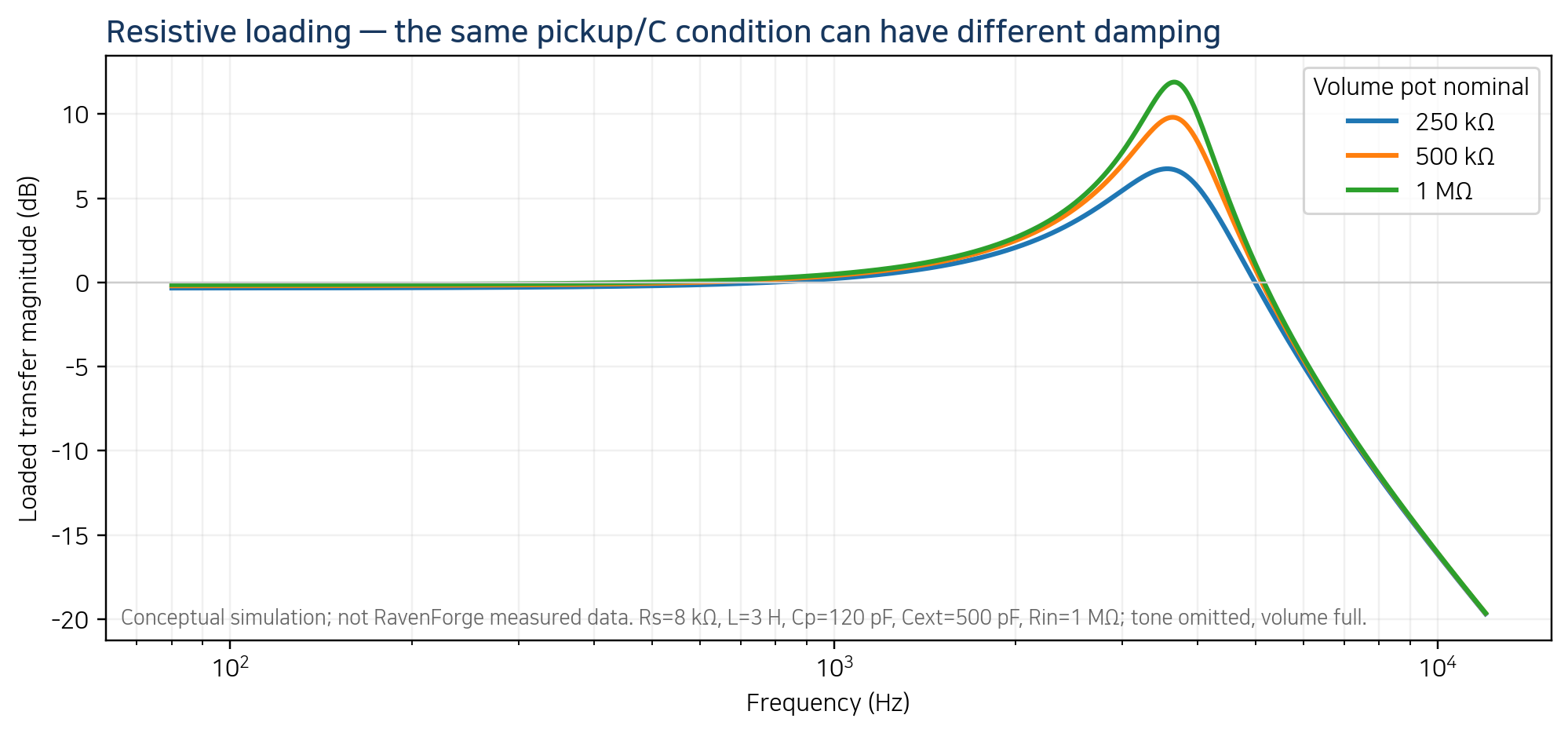
Figure 2. Conceptual comparison of 250 kΩ / 500 kΩ / 1 MΩ resistive loading.
Illustrative calculation, not RavenForge pickup measurement. The pot values in the legend combine in parallel with fixed Rin=1 MΩ.
4. Capacitive loading — manage cable by total capacitance, not length alone
An instrument cable is a distributed structure, but at typical instrument-cable lengths and audio frequencies its electrical length is very small, so a lumped shunt-capacitance approximation is practical. For the same construction, total capacitance scales approximately with capacitance per unit length times length, while connectors, patches, and device input capacitance add to the assembled path. Measured total pF is therefore a more direct loading descriptor than “3 m cable.”
Paiva & Penttinen found that, under their measurement and simulation conditions, cable capacitance dominated the audible-band loading effect while cable inductance and series/parallel resistance were negligible [1]. This does not mean low-capacitance cable is universally superior. Lower capacitance tends to move the loaded resonance upward for a given pickup, making it a voicing choice rather than a quality score. As one official example, Canare specifies 160 pF/m nominal capacitance for GS-6 [8].
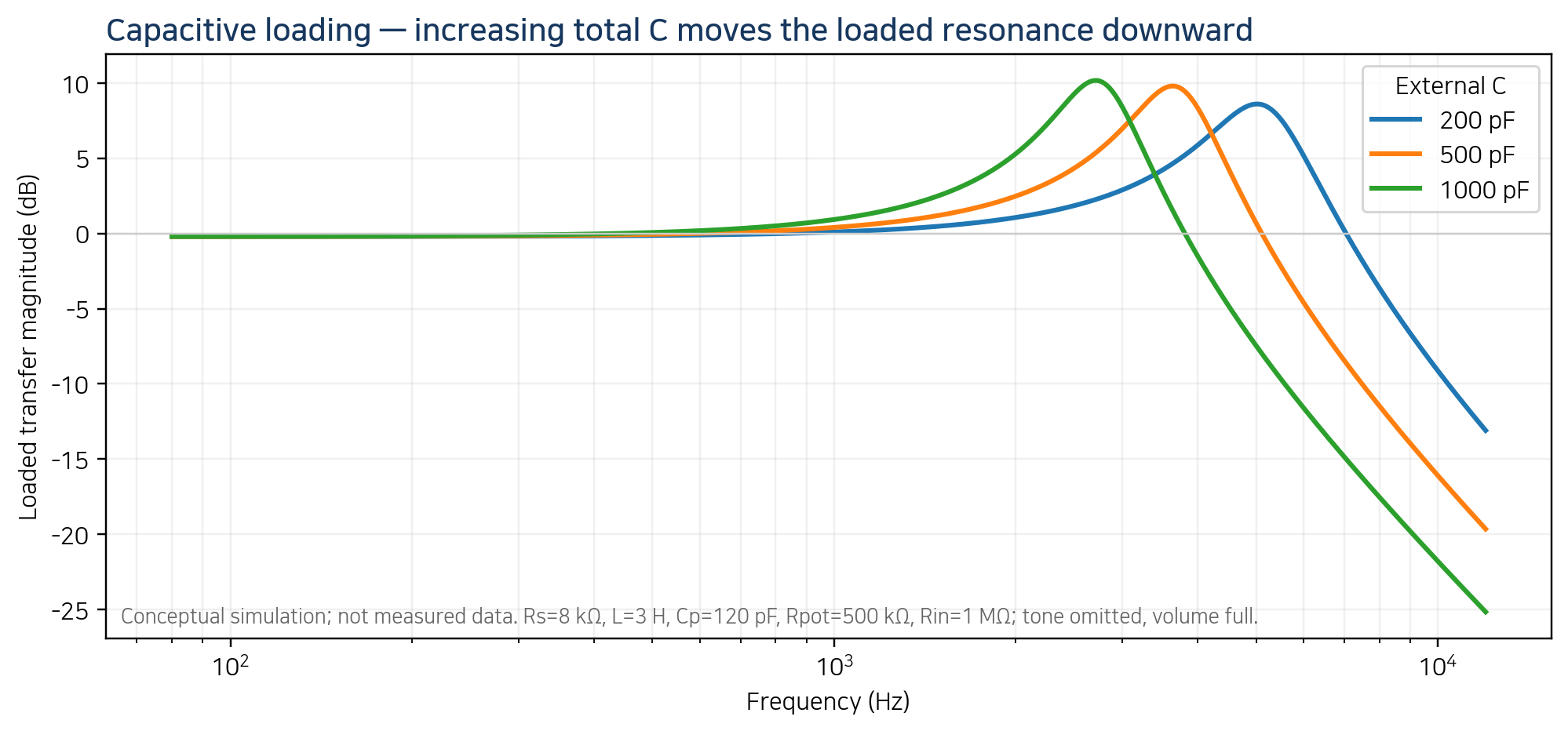
Figure 3. Conceptual effect of external capacitance on the loaded response.
Illustrative calculation varying only Cext for the same pickup/load. The pF values are test points, not cable quality grades.
5. Input impedance — 1 MΩ is not “unloaded”
Amp, pedal, DI, and interface inputs have finite resistance and parasitic/input capacitance. Input resistance loads the pickup node resistively, while input capacitance can add to cable capacitance at the same node. A “1 MΩ input” may be high impedance, but it is not infinity; even a no-cable bench measurement still contains probe and fixture capacitance.
RavenForge therefore uses specified high-impedance / specified-capacitance fixture rather than “unloaded.” In product comparisons, record Rin, Cin, and cable/patch configuration when possible instead of relying on an input label alone. The mechanism by which a buffer isolates downstream cable capacitance is treated formally in A05.
6. Volume control — lowering the knob changes level and topology
When a conventional passive volume pot moves away from full, input-to-wiper resistance Ra and wiper-to-ground resistance Rb appear. The downstream cable/input is connected at the wiper, so it forms a parallel or compound network with Rb, while Ra becomes a series path between pickup and output. The result is not only attenuation: wiper source impedance and cable capacitance can also reshape the frequency response.
Audio/log taper defines the resistance-versus-rotation law; it does not change the circuit topology. A treble-bleed network is a separate frequency-dependent bypass intended to compensate some state-dependent loss, not a universal restoration of the full-volume response. “Volume down = same tone, lower level” is generally false for an unbuffered high-impedance passive system.
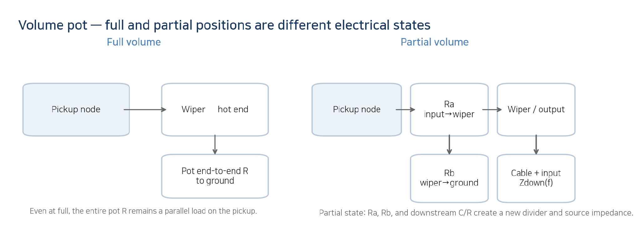
Figure 4. Different load states produced by a volume pot at full and partial settings.
Simplified topology. The actual response must include the tone branch and downstream input.
7. Tone control — at “10,” a standard tone branch does not completely disappear
A common passive tone control is a variable resistance Rt(θ) in series with capacitor Ct to ground. The branch may be written Ztone=Rt(θ)+1/(sCt), but the complete response must be solved with the pickup, volume, cable, and input network. With a standard pot, fully open still leaves a finite Rt, so the branch remains weakly coupled. A no-load tone pot is a distinct topology designed to physically disconnect the branch at its end position.
Values such as 22 nF or 47 nF are not universal answers for particular pickup types. The same capacitor behaves differently with different pickup inductance and load resistance. “Modern” and “50s” wiring likewise differ in which volume-pot node the tone branch uses; their volume-dependent interaction should be treated as a topology question, not as evidence that one is universally better.
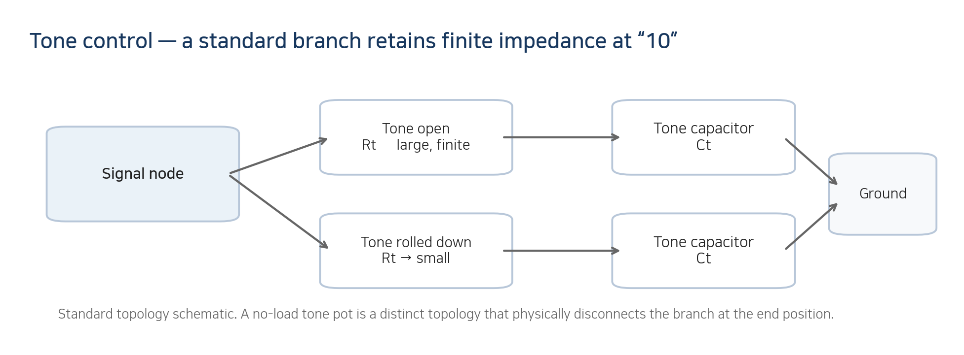
Figure 5. Conceptual knob states of a standard passive tone branch.
The Rt–Ct branch is part of the complete guitar network. A no-load pot is treated as a separate disconnect topology.
8. Multiple pickups — separate spatial mixing from electrical interaction
Selecting two passive pickups simultaneously combines the spatial sampling/phase effects discussed in A02 and also connects their source impedances and control networks. A parallel pickup combination is not merely an arithmetic sum of two voltages; in series/parallel switching and independent V/V wiring, each pickup can become part of the other pickup’s load. Each selector state should therefore be logged and measured as a separate loaded state.
9. Evidence matrix — what can A04 actually claim?
Claim | Assessment | A04 treatment |
500 kΩ is always brighter than 250 kΩ | Conditional | With the same topology/pickup/C, higher R usually reduces damping, but brightness and peak position depend on the whole network. |
1 MΩ is always best / most open | Unsupported value judgment | Higher R can reduce loading; optimum value is a target-response/interface decision. |
250 kΩ = single coil; 500 kΩ = humbucker | Convention, not a physical law | Do not choose load from pickup category label alone. |
Pot value changes intrinsic pickup R/L/C | Needs correction | It changes the loaded transfer condition, not the coil parameters themselves. |
Rload changes Q only, never peak frequency | Incorrect | Even the simple second-order transfer shows finite damping can shift the transfer peak. |
Longer cable always makes tone worse | Incorrect | For the same cable construction, C tends to increase; “worse” is a value judgment and total C must be measured. |
Low-capacitance cable is always superior | Unsupported | It is a voicing choice that tends to move resonance upward. |
1 MΩ input is effectively unloaded | Needs correction | R is finite and Cin/fixture C remain. |
Volume knob changes level only | Incorrect | Partial wiper state changes source impedance and its interaction with downstream C. |
Tone at 10 removes the tone circuit | Topology-dependent | Standard pots leave a finite branch; a no-load pot may disconnect it at the end position. |
22 nF / 47 nF has a correct pickup type | Unsupported | Result depends on L, Rload, and topology. |
Two pickups in parallel simply add signals | Needs correction | Their source impedances and controls also load each other. |
Cable C after a buffer changes passive pickup resonance the same way | Move to A05 / generally false | With adequate buffer isolation, downstream C is separated from the pickup node. |
10. C02 — Pickup Loading Measurement protocol
The literature and circuit results become a RavenForge specification only after effect size is measured on the actual pickup/load combination. C02 should hold pickup baseline and excitation fixed, substitute controlled Rload/Cload conditions, and compare Hloaded(f). Do not invent a universal “significant” threshold in advance; estimate repeatability and measurement uncertainty first, then compare measured effect size with the voicing target.
Stage | Record / condition | Decision |
1. Baseline | Fix pickup mounting/excitation, temperature, and wiring state | lock reference state |
2. Component metrology | Measure pot end-to-end R, taper position, cable/fixture total C | separate nominal from actual |
3. R-load matrix | Set Rload with precision resistor or measured pot | isolate resistive effect |
4. C-load matrix | Set Cload with known C / measured cable / fixture Cin | isolate capacitive effect |
5. Transfer sweep | Measure magnitude + phase Hloaded(f) with the same excitation | frequency-dependent effect |
6. Feature extraction | fpeak, peak gain, bandwidth/Q when valid | do not force Q if no clear peak |
7. Repeatability | Reconnect/reposition/repeat and estimate uncertainty | is effect larger than measurement noise? |
8. Archive | Store raw complex data + exact topology + metadata | traceable design rule |
For every state, record measured pot R, total C, fixture Rin/Cin, and wiring state. If a peak is well defined, extract fpeak, peak gain, and bandwidth/Q; otherwise retain the full complex H(f) and fitting residuals.
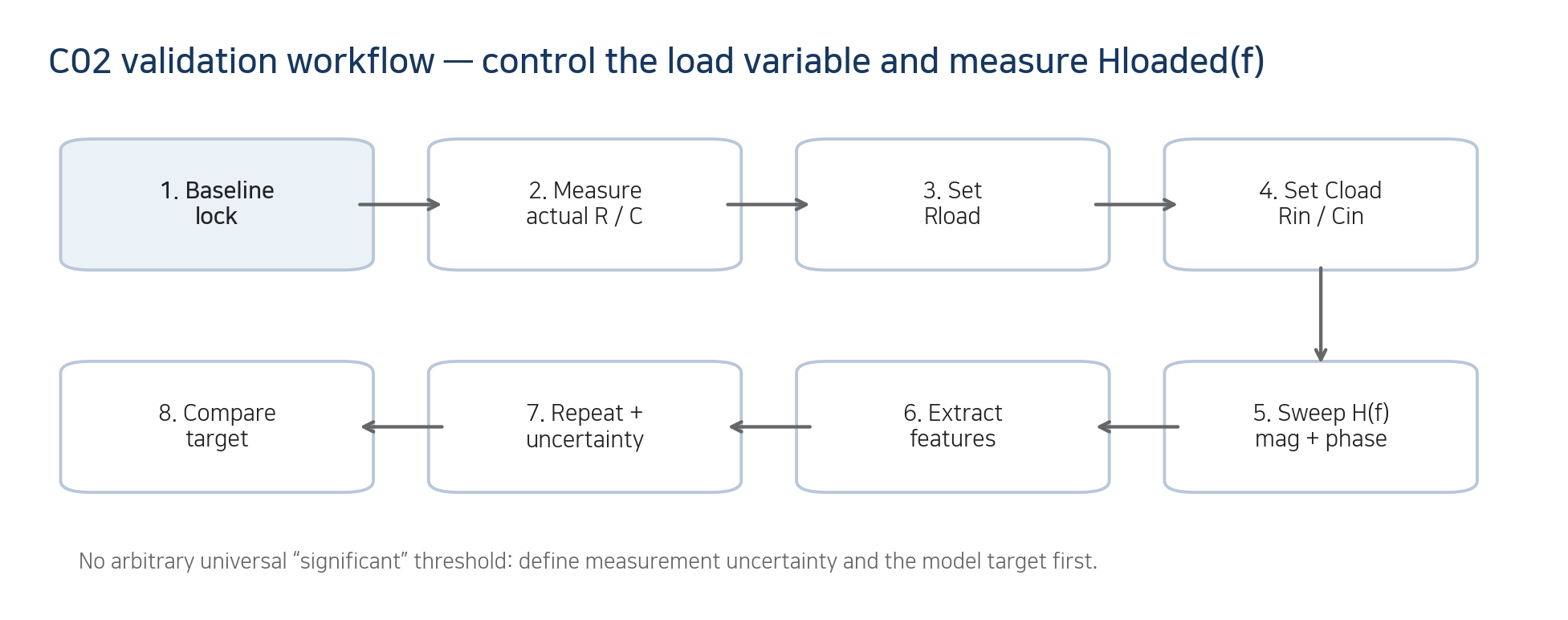
Figure 6. RavenForge loaded-response validation workflow leading to C02.
Engineering validation loop. An effect-size threshold is not fixed before measurement uncertainty and the model target are known.
11. RavenForge application — derive the load from target response, not convention
EDDA’s passive baseline should not begin with a recipe such as “vintage means 250 kΩ.” Define pickup Z(f), the target loaded response, and a reference cable/input condition, then select the pot/capacitor topology. Heritage is a decision about which historical system behavior to preserve, not a requirement to copy nominal part values.
If EMBLA/ASKR place an onboard buffer or preamp after a passive pickup, the input condition seen directly by the pickup can remain A04 metadata, while buffer output impedance and downstream cable isolation belong to A05. Current powered EMG/Fishman architectures should not be directly ranked with the traditional passive-loading model used here.
12. Current conclusion — passive-pickup output is a pickup-plus-load system property
A04 rejects the use of 250 kΩ, 500 kΩ, 1 MΩ, cable length, or “high-Z” as self-contained tone adjectives. In the reference topology, resistive loading governs damping and peak height, while capacitive loading combines with inductance to move the resonance. At partial volume, with tone networks, or with multiple pickups, the topology itself changes and must be modeled or measured in its actual wiring state.
Current design position RavenForge specification rule: pickup model + wiring state + measured pot resistance/taper position + total external capacitance + destination input condition → loaded-response target → C02 validation. Nominal component categories are implementation choices, not the target. |
13. Next research — what moves to C01 / C02 / A05
Code | Research question | Variables handed off from A04 |
C01 | Pickup Position FFT Mapping | measured validation of the A02 spatial-sampling model |
C02 | Pickup Loading Measurement | validation of the A04 R/C load matrix and Hloaded(f) |
A05 | Active Buffers and Input Impedance | pickup-facing Zin, low-Z output, cable isolation |
References
[1] Cauduro Dias De Paiva, R.; Penttinen, H. “Cable Matters: Instrument Cables Affect the Frequency Response of Electric Guitars.” 131st Convention of the Audio Engineering Society, Paper 8466, pp. 1–10 (2011). Aalto research portal classifies the conference publication as scientific / peer-review.
[2] Paiva, R. C. D.; Pakarinen, J.; Välimäki, V. “Acoustics and Modeling of Pickups.” Journal of the Audio Engineering Society 60(10), 768–782 (2012).
[3] Paiva, R. C. D. Circuit Modeling Studies Related to Guitars and Audio Processing. Aalto University doctoral dissertation (2013). Includes Publication II: Paiva & Penttinen (2011). ISBN 978-952-60-5388-2.
[4] Lemme, H. Electric Guitar: Sound Secrets and Technology. Elektor International Media, 2012. Technical monograph; not treated as peer-reviewed journal evidence.
[5] Lemme, H. E. W. “The Secrets of Electric Guitar Pickups.” Technical article / measurement notes, BuildYourGuitar resource; accessed 2026-09. Used for circuit/measurement practice, not as peer-reviewed evidence.
[6] Bourns. Model 82 Vintage Guitar Potentiometer product data: 250 kΩ / 500 kΩ range, standard resistance tolerance ±10%. Official manufacturer datasheet/product page.
[7] Bourns. Model 95 Premium Guitar Potentiometer datasheet: 25 kΩ, 50 kΩ, 250 kΩ, 300 kΩ, 500 kΩ values; total resistance tolerance ±20%. Official manufacturer datasheet.
[8] Canare. GS-6 Guitar / Instrument Cable official specifications: nominal capacitance 160 pF/m. Used only as an example of manufacturer-declared capacitance-per-length, not a universal cable value.
[R1] RavenForge / Signal & Transduction Research Log A03. “Magnetic Pickups as RLC Systems.” Figure-corrected revision, 2026.09.09.
[R2] RavenForge / Signal & Transduction Research Log A02. “Pickup Position and Harmonic Sampling.” Verified revision, 2026.09.06.
[R3] RavenForge / Design Methodology Research Log B02. “Voicing Before Specification.” 2026.09.08.
Source status and interpretation boundary [1] is classified by Aalto University’s research portal as a peer-reviewed scientific conference publication; [2] is a peer-reviewed JAES journal article, and [3] is an Aalto doctoral dissertation. Lemme/Zollner-type sources are used as technical literature/monographs and are not presented as peer-reviewed evidence. Bourns/Canare documents are used only for component specifications. The RavenForge reference transfer equation, Evidence Matrix, and C02 protocol are engineering frameworks derived from these sources and are not model-specific performance claims until prototype measurement. |
Working research document · 2026.09.10