RAVENFORGE / SIGNAL & TRANSDUCTION RESEARCH LOG — A03
RAVENFORGE
Signal & Transduction Research Log
A03 — Magnetic Pickups as RLC Systems
분포권선 전자기 변환기를 1차 등가회로로 읽고, DCR·Z(f)·공진·Q를 분리하는 방법
문서 목적 패시브 magnetic pickup을 “저항값이 높은 코일”이나 단순한 tone adjective로 설명하지 않고, 현의 운동을 유도 기전력로 변환하는 전자기적 source와 주파수 의존 terminal impedance를 분리해 모델링한다. R–L–C 등가회로가 유효한 범위와 한계를 명시하고, DCR·inductance·distributed capacitance·resonance·Q·eddy-current loss를 공통 측정 언어로 정리한다. 외부 pot/cable loading의 상세는 A04, buffer/interface는 A05, 실제 pickup의 Z(f)와 magnetic transfer function 실측은 후속 C-log로 넘긴다. |
Code | A03 |
Focus | passive pickup equivalent network · DCR · complex Z(f) · resonance · Q · winding · magnetic/eddy-current losses |
Evidence | JAES / American Journal of Physics / IEEE Transactions on Magnetics · technical monographs · controlled winding preprint |
RavenForge link | ASKR / EMBLA / EDDA pickup selection and characterization |
Downstream logs | A04 Electrical Loading · A05 Active Buffers · C-series pickup characterization |
Status | First-order electrical framework verified · model-specific values pending measurement |
1. 연구 질문 — “픽업은 RLC 회로다”라고 어디까지 말할 수 있는가
A01은 magnetic pickup을 mechanical domain과 electrical domain 사이의 electromechanical transducer로 정의했고, A02는 pickup 위치와 spatial harmonic sampling을 다뤘다. A03의 질문은 더 좁다. 실제 패시브 pickup의 단자에서 보이는 전기적 거동을 R, L, C로 어느 정도 설명할 수 있으며, 그 모델을 pickup의 전체 물리와 혼동하지 않으려면 어떤 경계를 그어야 하는가?
Horton & Moore와 Lemarquand & Lemarquand의 모델은 현–영구자석–코일 시스템에서 움직이는 강자성 현이 자기장을 교란하고, 그 자속 변화가 Faraday 법칙을 통해 EMF를 만든다는 source mechanism을 다룬다 [1,2]. 반면 Paiva 등과 Lemme/Zollner의 electrical treatment는 pickup의 위치·감지 폭·선형 공진 filtering 및 terminal impedance를 별도 층위로 다룬다 [3–5]. 따라서 A03은 “source model”과 “terminal equivalent model”을 의도적으로 분리한다.
핵심 관점 A passive magnetic pickup is not literally an ideal RLC circuit. It is an electromagnetic transducer whose terminal behaviour can be approximated, over a limited frequency range, by a lumped resonant network. |
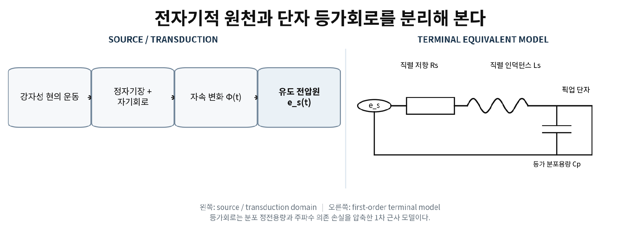
Figure 1. 전자기적 source와 terminal equivalent circuit의 분리.
RavenForge 개념도. 오른쪽 R–L–C는 first-order lumped approximation이며 실제 분포권선과 손실 branch를 모두 표현하지 않는다.
2. 1차 등가회로 — 전압원과 terminal impedance를 구분한다
가장 흔한 first-order model은 induced source eₛ(t)에 직렬 권선저항 Rₛ와 등가 인덕턴스 Lₛ가 있고, 그 branch 양단에 권선의 distributed capacitance를 하나의 Cₚ로 환산해 병렬로 둔 구조다 [4,5]. 전압원을 0으로 놓고 단자에서 본 임피던스는 다음과 같이 쓸 수 있다.
Zpu(ω) = [ 1 / (Rₛ + jωLₛ) + jωCₚ ]⁻¹
이 식은 특정 topology의 lumped approximation이다. 실제 winding은 turn-to-turn/layer-to-layer capacitance를 가진 distributed network이며, steel poles, blades, keeper/baseplate와 같은 conductive magnetic parts는 eddy-current loss와 frequency-dependent apparent inductance를 만든다. 따라서 fitted R/L/C는 raw Z(f)를 대체하는 “진짜 물성값”이 아니라 제한된 대역을 압축하는 engineering descriptor다.
모델 경계 RavenForge에서는 raw complex Z(f)를 1차 데이터로 보존하고, R/L/C/Q는 측정 조건과 fitting error를 함께 기록하는 요약 파라미터로 사용한다. |
3. 공진 — self resonance, impedance peak, transfer peak를 섞지 않는다
lossless LC의 자연주파수 f₀ = 1/(2π√LC)는 useful intuition이지만, 실제 pickup에는 winding resistance와 추가 손실이 있다. 더구나 “resonance”를 무엇의 peak로 정의하는지에 따라 조건이 달라진다. 위의 (R+jωL)∥C topology에서 admittance의 imaginary part가 0이 되는 phase-zero condition과 |Z|가 최대가 되는 조건은 finite R에서 일반적으로 완전히 같은 식이 아니다. 따라서 A03은 특정 closed-form 식을 universal pickup resonance formula로 고정하지 않는다.
가장 안전한 표기는 측정량을 직접 이름 붙이는 것이다. 예를 들어 `fZ,max = frequency of maximum |Z(f)| under the stated fixture`, `fφ0 = zero-crossing of terminal phase`, `fH,max = peak of magnetic-excitation→voltage transfer response`처럼 기록한다. 이 세 값은 related하더라도 동일하다고 가정하지 않는다. external pot/cable/input가 연결되면 또 다른 loaded response가 형성되며, 그 상세는 A04의 범위다.
용어 원칙 “Self-resonant frequency”라는 단일 숫자를 제시할 때는 측정 topology와 criterion을 반드시 붙인다. `Impedance resonance`와 `transfer-response peak`는 서로 교환 가능한 용어가 아니다. |
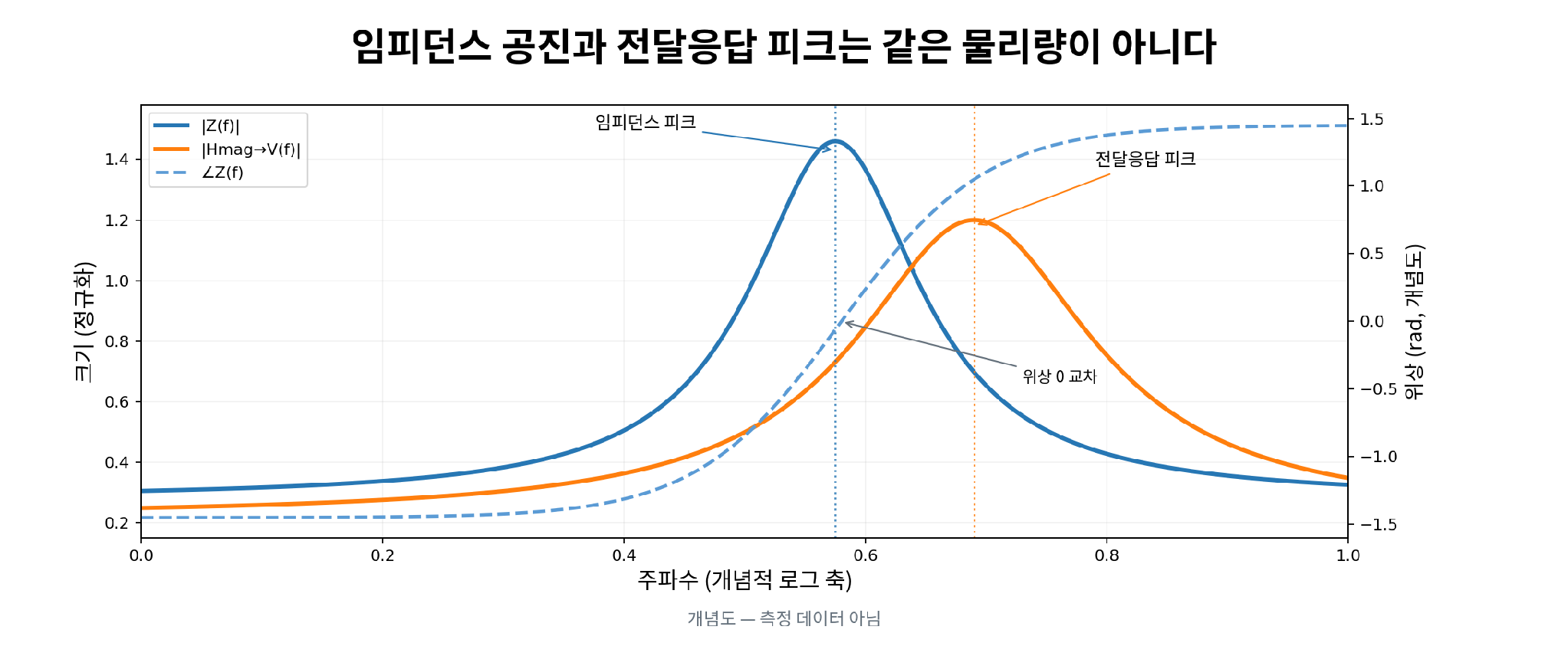
Figure 2. Complex Z(f)와 magnetic transfer H(f)의 공진 기준 분리.
개념도이며 실측 데이터가 아니다. 실제 pickup에서는 loss와 measurement topology에 따라 각 peak/zero-crossing 위치가 달라질 수 있다.
4. DCR — 유용한 제작 정보지만 universal output/tone metric은 아니다
DC resistance는 기본적으로 R = ρl/A로 결정된다. 따라서 total wire length, conductor cross-section, resistivity와 온도의 영향을 직접 받는다. NIST copper data는 약 20 °C 부근에서 resistance가 온도에 민감하게 변한다는 점을 명확히 보여준다 [6,7]. 같은 pickup도 온도가 달라지면 DCR이 변하므로 비교표에는 측정 온도를 남겨야 한다.
동일 bobbin, 동일 wire gauge, 동일 magnetic structure와 winding method에서 turns만 달라지는 controlled family라면 DCR은 wire length/turn count의 proxy가 될 수 있다. 그러나 AWG, bobbin dimensions, lead length, coil packing과 magnetic circuit이 다른 픽업 사이에서 “17 kΩ가 9 kΩ보다 더 hot하다/더 dark하다”는 식으로 직접 비교할 수는 없다. DCR에는 magnet-to-string coupling이나 output transfer sensitivity가 직접 들어 있지 않는다.
설계 원칙 DCR is a winding/manufacturing descriptor first. It becomes a useful proxy only inside a sufficiently controlled pickup family. |
5. Inductance와 distributed capacitance — 단일 숫자 뒤의 조건을 기록한다
ideal solenoid의 L ∝ μN²A/l 관계는 방향성을 설명하는 데는 유용하지만 guitar/bass pickup은 closed magnetic circuit이 아니다. Leakage, fringing, pole/blade/core permeability, steel hardware와 coil shape가 함께 관여하고, eddy currents와 magnetic losses 때문에 LCR meter가 보고하는 apparent L가 frequency와 equivalent-series/parallel mode에 따라 달라질 수 있다 [2,5]. 따라서 “L = 5 H”만 적는 것은 불충분하다.
Capacitance도 하나의 물리 capacitor가 아니다. 실제 권선은 turn-to-turn, layer-to-layer, coil-to-core/cover, lead 및 fixture capacitance가 분포된 구조다. 단일 Cₚ는 low-order equivalent model을 위해 fitting한 값이다. Scatter winding이 평균 coupling capacitance를 낮출 가능성은 물리적으로 plausible하지만, pickup-specific controlled peer-reviewed evidence는 아직 약하다. RavenForge에서는 이를 검증된 법칙이 아니라 measurement hypothesis로 남긴다.
6. Turns와 wire gauge — “출력만” 바뀌지 않는다
Faraday-law intuition에서 induced EMF는 winding turns N에 따라 증가할 수 있지만, 실제 winding에서 N을 늘리면 wire length와 R이 늘고, L은 대체로 증가하며, distributed capacitance와 coil dimensions/fill도 함께 변한다. 따라서 turns는 하나의 독립적인 “hotness knob”가 아니다.
Batchelor 등은 Strat-style test coils에서 5,000–12,000 turns와 42/44 AWG를 비교하고 impedance analyser로 resonance behaviour가 turns와 gauge에 따라 달라진다는 controlled dataset을 제시했다 [8]. 그러나 확인되는 publication status는 arXiv preprint이며, impedance-peak magnitude를 실제 moving-string output sensitivity와 동일한 물리량으로 일반화해서는 안 된다. 이 연구는 “turns/gauge가 Z(f)를 바꾼다”는 근거로는 유용하지만, 모든 pickup의 실제 playing output을 직접 예측하는 보편 법칙은 아니다.
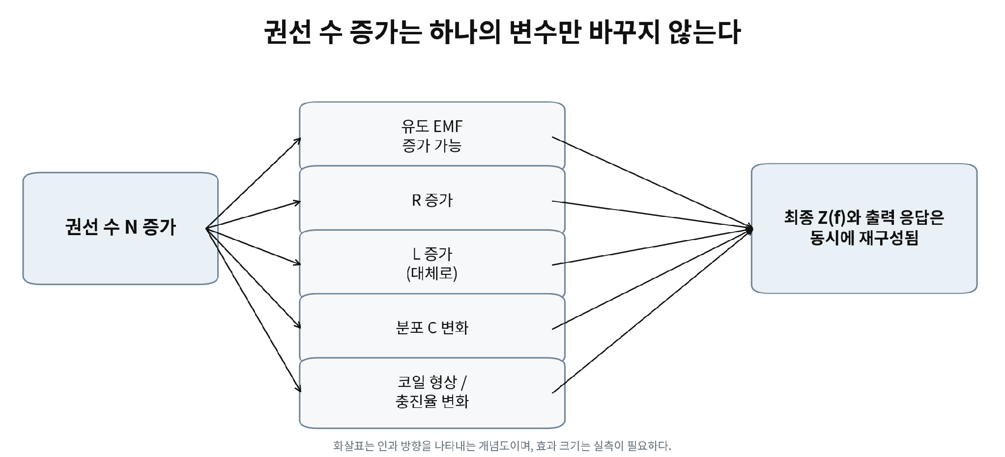
Figure 3. 권선 수 증가가 여러 전기·기하 변수를 동시에 바꾸는 causal map.
정성적 방향을 보여주는 RavenForge working model. Effect size는 pickup architecture별 실측이 필요하다.
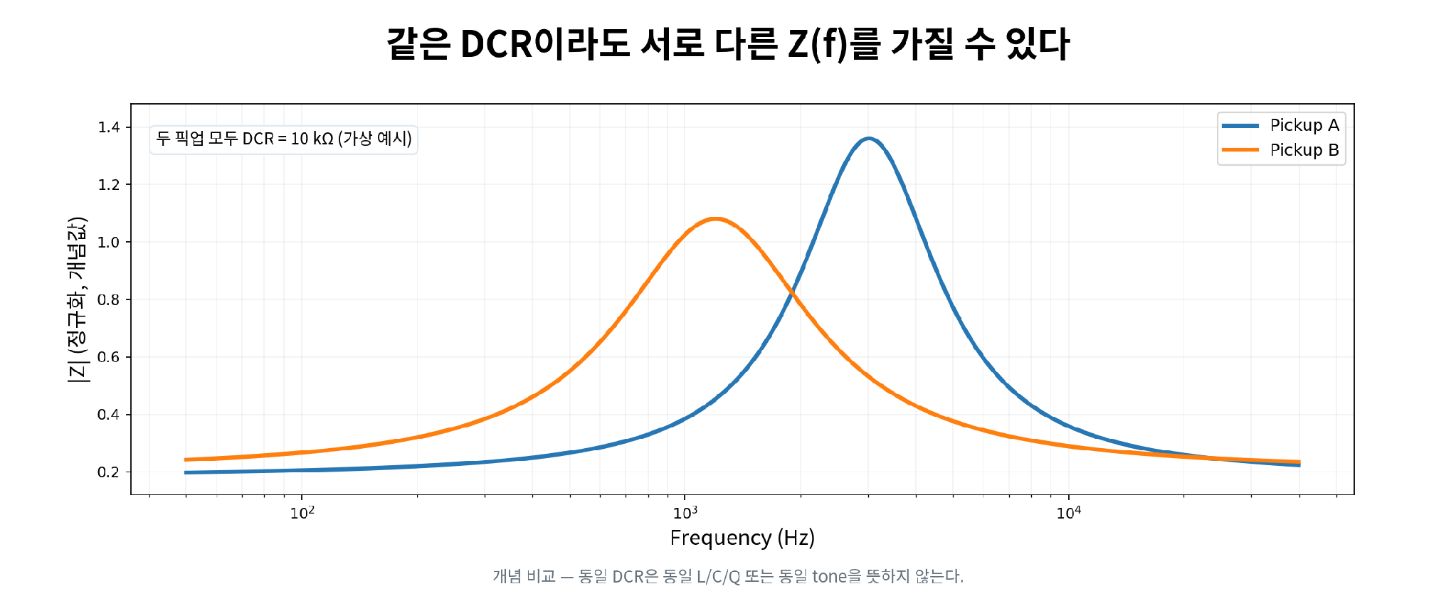
Figure 4. 동일 DCR이 동일한 주파수 의존 impedance를 보장하지 않는 이유.
가상 곡선. “10 kΩ” 하나로 L/C/Q 또는 실제 transfer response를 결정할 수 없음을 보여주는 conceptual comparison이다.
7. Magnetic circuit, metal parts와 eddy-current loss
Magnet material name을 곧바로 warm/bright/aggressive 같은 adjective로 번역하는 대신, A03에서는 source sensitivity와 terminal impedance에 작용하는 경로를 나눈다. 영구자석의 static flux와 string coupling은 source term에 우선적으로 관여하고, pole/blade/core의 permeability와 conductive steel, baseplate, cover는 L(f), loss와 Q에 영향을 줄 수 있다 [2,5].
Lemme의 기술 측정자료에서는 일부 commercial pickup에서 metal casing 유무에 따라 resonance/Q가 달라지는 사례가 보고된다 [4]. 이는 cover/baseplate를 tone adjective로 외우기보다 conductivity, permeability, thickness, geometry, continuity를 기록하고 Z(f)를 직접 비교해야 함을 시사한다. Nickel-silver가 brass보다 대체로 덜 conductive하다는 재료 특성만으로 “electrically transparent”라고 단정할 수는 없다.
8. Z(f)와 H(f) — impedance 측정은 pickup output 측정이 아니다
Complex terminal impedance Z(f)는 픽업 단자에 작은 전기적 자극을 가해 본 network property다. 반면 실제 연주에서 중요한 magnetic excitation→output transfer Hmag→V(f)는 외부 magnetic perturbation이 pickup output voltage로 변환되는 transduction property다. 두 곡선은 연관되지만 동일하지 않다.
Horton/Moore와 Lemarquand의 연구는 source mechanism의 nonlinearity와 geometry를 보여주며 [1,2], Lemme는 moving string 대신 calibrated transmitting/excitation coil로 pickup을 여기해 transfer response를 측정하는 실용적인 방법을 소개한다 [4]. 따라서 RavenForge bench characterization은 Z(f) sweep과 H(f) measurement를 별도 channel로 기록하는 편이 맞다.
측정 경계 Impedance peak ≠ output peak. Z(f)는 “픽업이 전기적으로 어떻게 보이는가”, H(f)는 “자기적 입력을 얼마나/어떻게 전압으로 바꾸는가”를 묻는다. |
9. Active pickup은 별도 architecture class다
EMG와 Fishman Fluence 같은 powered pickup은 내부 transducer 뒤에 active electronics가 결합되어 출력 impedance와 voice/transfer behaviour가 형성된다. 예를 들어 EMG 40-TW-X는 공식 문서에 2 kΩ output impedance를, Fishman Fluence Bass Soapbar는 9.4 kΩ output impedance와 current draw를 명시한다 [9,10]. 이 수치는 해당 모델의 완성된 output architecture에 대한 값이며, passive coil의 DCR/L/C와 같은 의미가 아니다.
따라서 passive high-impedance pickup과 active/powered pickup을 하나의 DCR–L–C–Q ranking으로 비교하면 category error가 생긴다. 공통 비교가 필요한 경우 architecture class, transduction topology, output/source impedance, transfer behaviour, required interface/load, noise, headroom/current와 같은 기능 수준의 변수를 사용한다.
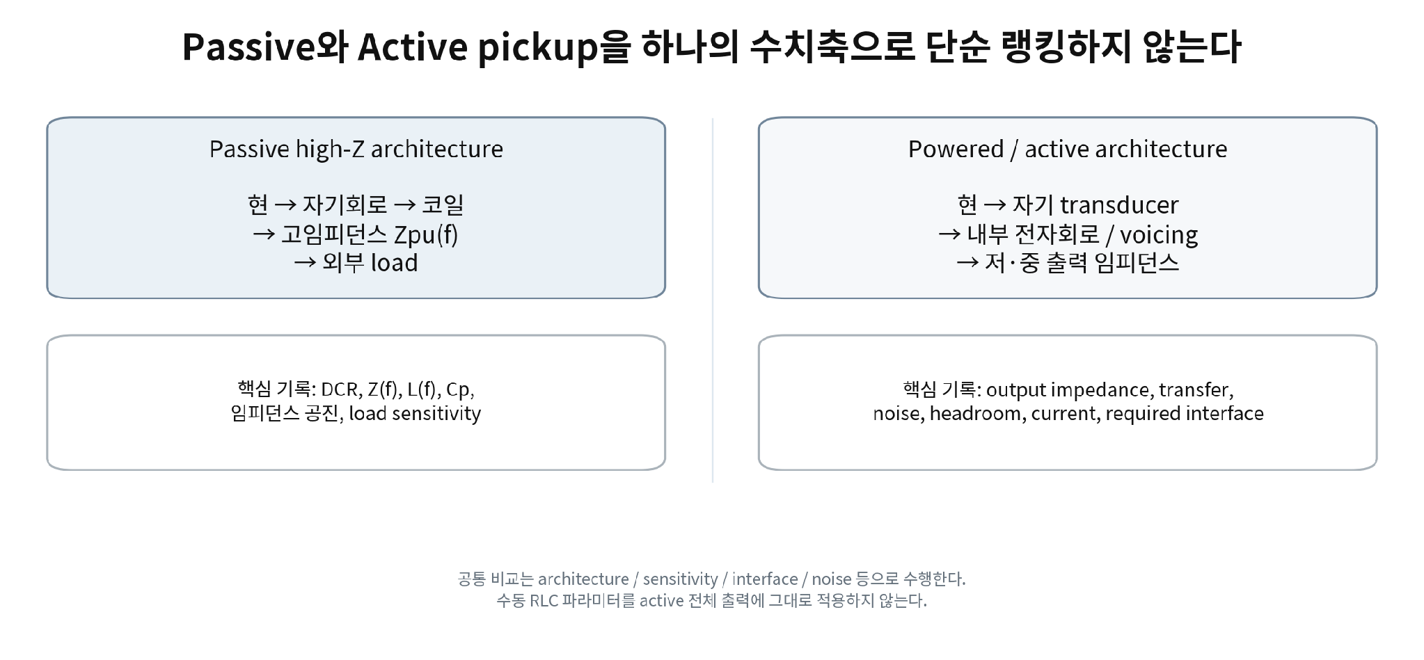
Figure 5. Passive high-Z와 powered/active pickup의 architecture boundary.
공통 기능은 비교할 수 있지만 passive coil의 RLC 지표를 active pickup 전체 출력에 직접 적용하지 않는다.
10. 근거 매트릭스 — A03에서 어디까지 주장할 수 있는가
Claim | Assessment | RavenForge wording |
DCR이 높으면 output이 더 세다 | Correct but conditional | 동일 family에서만 turns/length proxy가 될 수 있음; 브랜드 간 universal rule 아님 |
DCR이 높으면 더 dark/warm하다 | Unsupported as standalone rule | L/C/Q/source/load가 함께 결정 |
Inductance가 높으면 무조건 dark하다 | Too strong / conditional | resonance와 damping은 C, losses, load와 결합 |
Turns가 많으면 output만 증가한다 | Incorrect | R/L/C/geometry와 transduction sensitivity가 함께 변함 |
Scatter winding은 C를 낮춰 더 open하다 | Plausible, requires measurement | 물리적으로 가능하나 pickup-specific controlled evidence 부족 |
AWG43은 AWG42보다 hot하다 | Unsupported standalone claim | wire resistance/packing/turn count와 분리 불가 |
Resonant frequency 하나면 tone을 예측한다 | Too strong | Q, transfer sensitivity, spatial sampling, load 필요 |
Passive pickup은 RLC circuit이다 | Correct only as first-order equivalent model | 실제 분포권선/손실/전자기 source를 단순화한 모델 |
Active pickup도 passive RLC로 직접 비교 가능 | Incorrect / architecture-dependent | complete output architecture가 다름 |
500k pot이 pickup intrinsic R/L/C를 바꾼다 | Move to A04 / needs correction | coil parameters 자체보다 loaded system peak/Q를 바꿈 |
Impedance peak = actual output peak | Incorrect simplification | Z(f)와 Hmag→V(f)는 다른 물리량 |
Q가 높을수록 좋은 pickup이다 | Incorrect | resonance damping descriptor이지 품질점수 아님 |
Metal cover는 무조건 treble을 깎는다 | Too strong | conductivity/permeability/geometry에 따라 effect size가 달라짐 |
Nickel silver cover는 electrically transparent하다 | Unsupported absolute claim | loss가 작을 수 있어도 0이라고 단정 불가 |
11. RavenForge Pickup Characterization Protocol
A03의 목적은 spec-sheet 숫자를 늘리는 것이 아니라 측정 가능한 공통 언어를 만드는 것이다. 실제 bench test에서는 “unloaded”라는 표현보다 fixture의 입력 impedance/capacitance를 명시한 specified high-impedance condition을 사용한다. 완전한 무부하는 존재하지 않으며 lead/fixture parasitic도 측정에 들어간다.
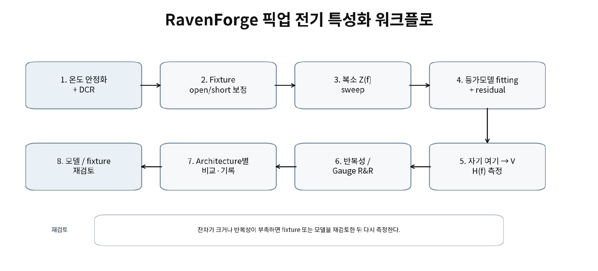
Figure 6. RavenForge pickup electrical & transfer characterization workflow.
Z(f)와 H(f)를 별도 channel로 측정하고 fixture compensation, fit residual, repeatability를 함께 보존한다.
Stage | Record / condition | Decision |
Temperature stabilize | pickup, fixture and meter temperature; allow thermal equilibrium | DCR comparability |
DCR | 4-wire/compensated method when practical; record °C and lead condition | winding descriptor |
Fixture compensation | open/short; known reference where available; fixed lead length and shielding | remove fixture parasitics |
Complex Z(f) | magnitude + phase sweep; stated excitation level and range | primary electrical data |
Model fit | fit R/L/C or extended network; store residuals and validity band | compact descriptor, not replacement data |
Magnetic H(f) | controlled excitation coil or moving-string fixture; fixed geometry | transduction response |
Hardware state | cover/baseplate/poles/string proximity/orientation recorded | reproducibility |
Repeatability | re-seat pickup; repeated sweep; Gauge R&R | measurement uncertainty |
Archive | raw complex data, calibration, instrument settings, photos | traceable dataset |
12. RavenForge 비교 프레임 — Delano / Turner / Herrick / Nova와 EMG / Fishman을 어떻게 같은 표에 둘 것인가
Field | Passive high-Z class | Powered / active class |
Architecture | coil topology / hum-cancel / multicoil state | transducer + internal electronics / voice topology |
DCR | record @ temperature | not a direct whole-system comparison metric |
Complex Z(f) | core metric | output Z(f) may be relevant, but not equivalent to passive coil Z(f) |
L(f), Cp, impedance resonance | characterization metrics | usually internal/transducer-level only |
Magnetic→V transfer | core metric | core metric at complete output |
Output/source impedance | frequency-dependent, often high | manufacturer/measurement value |
Required interface/load | A04 | manufacturer/interface requirement |
Noise | measure | measure |
Headroom / current / power | normally N/A | required where applicable |
Wiring state | each series/parallel/coil state measured separately | each voice/mode documented separately |
13. A03 / A04 / A05 / C-log 경계
Code | Scope |
A03 | pickup 자체의 equivalent impedance, DCR, Z(f), L/C/Q/loss, winding·magnetic·metal-part influence |
A04 | 250k/500k/1M pot, cable capacitance, amplifier/input impedance와 loaded response |
A05 | high-Z buffer input, low-Z output, cable isolation, active interface |
C03 proposed | 실제 pickup DCR + complex Z(f) + magnetic transfer H(f) characterization and Gauge R&R |
14. 현재 결론 — pickup spec을 “kΩ 하나”에서 frequency-dependent system으로 확장한다
A03에서 RavenForge가 채택하는 기본 단위는 DCR 하나가 아니라 `architecture + source mechanism + complex Z(f) + measurement condition + magnetic transfer H(f)`다. R/L/C는 useful first-order descriptors이지만 분포권선과 loss mechanisms를 완전히 대체하지 않는다.
따라서 pickup 선정에서 “더 높은 DCR”, “더 큰 inductance”, “더 높은 Q”를 독립적인 품질 서열로 사용하지 않는다. 어떤 model voice를 구현해야 하는지는 B02 Sonic Brief에서 시작하고, A02의 pickup coordinate, A03의 pickup electrical architecture, A04의 load, A05의 interface를 분리한 뒤 prototype data로 다시 결합한다.
현재 설계 입장 A pickup earns its place through measured and validated system behaviour, not through DCR, magnet material, wire gauge or boutique winding lore taken in isolation. |
15. 다음 연구 — A04로 넘기는 것
Code | Research question | 변수 / 목적 |
A04 | Electrical Loading of Passive Pickups | 250k / 500k / 1M pots, cable capacitance, input impedance, loaded resonance and Q |
C01 | Pickup Position FFT Mapping | A02 spatial sampling validation |
A05 | Active Buffers and Input Impedance | high-Z sensing, low-Z drive, cable isolation |
C03 proposed | Pickup Electrical & Transfer Characterization | DCR, Z(f), H(f), covers/baseplates, repeatability |
참고문헌
[1] Horton, N. G.; Moore, T. R. “Modeling the magnetic pickup of an electric guitar.” American Journal of Physics 77(2), 144–150 (2009). DOI: 10.1119/1.2990663.
[2] Lemarquand, G.; Lemarquand, V. “Calculation Method of Permanent-Magnet Pickups for Electric Guitars.” IEEE Transactions on Magnetics 43(9), 3573–3578 (2007). DOI: 10.1109/TMAG.2007.891671.
[3] Paiva, R. C. D.; Pakarinen, J.; Välimäki, V. “Acoustics and Modeling of Pickups.” Journal of the Audio Engineering Society 60(10), 768–782 (2012).
[4] Lemme, H. E. W. “The Secrets of Electric Guitar Pickups.” Technical article / guitar-electronics reference; updated 2026. Includes first-order pickup electrical models, measurement methods and resonance tables.
[5] Zollner, M. Physik des Magnettonabnehmers. Selbstverlag, Regensburg (2022), 287 pp. Technical monograph; pickup impedance, loss and equivalent-network treatment.
[6] Matula, R. A. “Electrical resistivity of copper, gold, palladium, and silver.” Journal of Physical and Chemical Reference Data 8(4), 1147–1298 (1979). DOI: 10.1063/1.555614.
[7] U.S. Bureau of Standards. Circular No. 31, Copper Wire Tables, 3rd ed. Resistance conversion at 20 °C and temperature coefficient ≈ 0.00393 K⁻¹ for standard copper wire calculations.
[8] Batchelor, C.; Gooding, J.; Marriott, W.; Chalashkanov, N.; Tucker, N.; Margetts, R. “Guitar Pickups I: Analysis of the Effect of Winding and Wire Gauge on Single Coil Electric Guitar Pickups.” arXiv:2409.19782 (2024). Preprint; peer-review status not verified.
[9] EMG Pickups. 40-TW-X installation/specification sheet, model 40-TW-X. Official manufacturer documentation; output impedance 2 kΩ for cited modes.
[10] Fishman. Fluence Bass Soapbar 5-String Pickups official specifications. Output impedance 9.4 kΩ; current draw and voice peak-frequency data for the cited model.
[R1] RavenForge / Signal & Transduction Research Log A01. “From Mechanical Vibration to Electrical Signal.” 2026.09.05.
[R2] RavenForge / Signal & Transduction Research Log A02. “Pickup Position and Harmonic Sampling.” Verified revision, 2026.09.06.
[R3] RavenForge / Design Methodology Research Log B02. “Voicing Before Specification.” 2026.09.08.
출처 상태 및 해석 범위 [1–3,6]은 peer-reviewed 또는 표준 학술 출처다. [4] Lemme와 [5] Zollner는 guitar-electronics 분야의 권위 있는 technical literature/monograph이지만 peer-reviewed journal paper와 구분한다. [8]은 controlled winding preprint이며 peer-review status가 확인되지 않았으므로 제한된 근거로 사용한다. [9–10] 제조사 문서는 해당 active architecture의 공식 사양 확인에만 사용한다. RavenForge의 measurement protocol, comparison schema와 C03 제안은 이 자료들을 악기 R&D에 적용한 internal engineering framework다. |
Working research document · 2026.09.09