RAVENFORGE / SIGNAL & TRANSDUCTION RESEARCH LOG — A03
RAVENFORGE
Signal & Transduction Research Log
A03 — Magnetic Pickups as RLC Systems
Reading a distributed electromagnetic transducer through a first-order equivalent network while separating DCR, Z(f), resonance and Q
Document purpose Model the passive magnetic pickup as an electromagnetic source plus a frequency-dependent terminal network rather than as a “high-resistance coil” or a collection of tone adjectives. Establish the valid scope and limitations of the R–L–C approximation and organize DCR, inductance, distributed capacitance, resonance, Q and eddy-current loss into a common measurement language. Detailed external loading is deferred to A04, buffer/interface behavior to A05, and actual Z(f) plus magnetic transfer measurements to a later C-log. |
Code | A03 |
Focus | passive pickup equivalent network · DCR · complex Z(f) · resonance · Q · winding · magnetic/eddy-current losses |
Evidence | JAES / American Journal of Physics / IEEE Transactions on Magnetics · technical monographs · controlled winding preprint |
RavenForge link | ASKR / EMBLA / EDDA pickup selection and characterization |
Downstream logs | A04 Electrical Loading · A05 Active Buffers · C-series pickup characterization |
Status | First-order electrical framework verified · model-specific values pending measurement |
1. Research question — How far can we say “a pickup is an RLC circuit”?
A01 defined the magnetic pickup as an electromechanical transducer between mechanical and electrical domains, and A02 treated pickup position and spatial harmonic sampling. A03 asks a narrower question: how much of the passive pickup’s terminal electrical behavior can be represented by R, L and C, and what boundaries prevent that model from being confused with the complete physics of the transducer?
Horton & Moore and Lemarquand & Lemarquand model the source mechanism: a moving ferromagnetic string perturbs the magnet/string field and the resulting flux variation produces EMF by Faraday induction [1,2]. Paiva et al. and the technical treatments of Lemme and Zollner address pickup-position coloration, linear resonant filtering and terminal electrical behavior as another layer [3–5]. A03 therefore deliberately separates the source model from the terminal equivalent model.
Core perspective A passive magnetic pickup is not literally an ideal RLC circuit. It is an electromagnetic transducer whose terminal behaviour can be approximated, over a limited frequency range, by a lumped resonant network. |
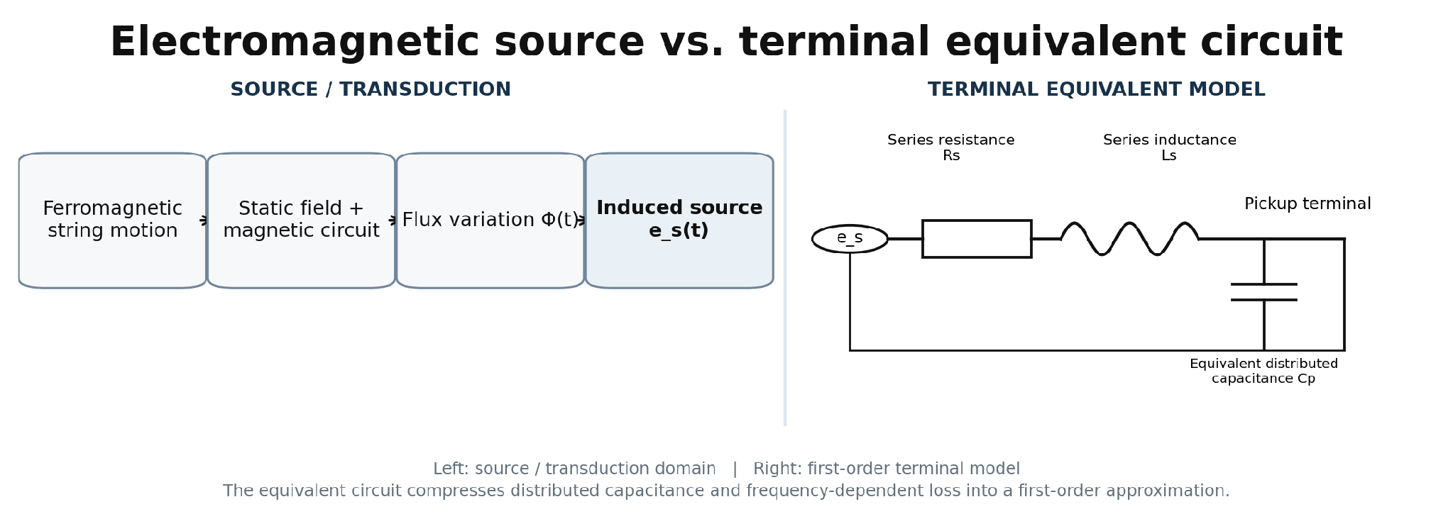
Figure 1. Separation of electromagnetic source and terminal equivalent circuit.
RavenForge schematic. The R–L–C network is a first-order lumped approximation and does not represent every distributed winding or loss branch.
2. First-order equivalent circuit — separate the voltage source from terminal impedance
A widely used first-order model consists of an induced source eₛ(t), series winding resistance Rₛ and equivalent inductance Lₛ, with the distributed winding capacitance collapsed into a shunt capacitance Cₚ across the branch [4,5]. With the source set to zero, terminal impedance can be written as:
Zpu(ω) = [ 1 / (Rₛ + jωLₛ) + jωCₚ ]⁻¹
This is a lumped approximation for one topology. A real winding is a distributed network of turn-to-turn and layer-to-layer capacitances, while conductive magnetic components such as steel poles, blades, keepers and baseplates introduce eddy-current loss and frequency-dependent apparent inductance. Fitted R/L/C values are therefore engineering descriptors over a stated band, not immutable “true material constants” that replace raw Z(f).
Model boundary RavenForge retains raw complex Z(f) as primary data. R/L/C/Q are compact descriptors reported together with the measurement condition, validity band and fitting error. |
3. Resonance — do not merge self resonance, impedance peak and transfer peak
The lossless LC relation f₀ = 1/(2π√LC) is useful intuition, but real pickups contain winding resistance and additional losses. More importantly, the resonance condition depends on what quantity is being maximized or zero-crossed. For the (R+jωL)∥C topology, the zero of imaginary admittance and the maximum of |Z| are not generally identical at finite R. A03 therefore does not promote one closed-form expression as a universal pickup-resonance formula.
The safer practice is to name the measured criterion directly: `fZ,max = frequency of maximum |Z(f)| under the stated fixture`, `fφ0 = terminal phase zero-crossing`, and `fH,max = peak of magnetic-excitation→voltage transfer response`. They are related but not assumed identical. Once pots, cable capacitance and input impedance are attached, another loaded response emerges; that is the detailed subject of A04.
Terminology rule Whenever “self-resonant frequency” is reported, the measurement topology and resonance criterion must be stated. `Impedance resonance` and `transfer-response peak` are not interchangeable. |
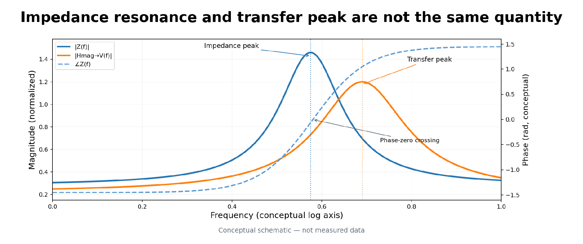
Figure 2. Separating resonance criteria in complex Z(f) and magnetic transfer H(f).
Conceptual only, not measured data. In real pickups, losses and measurement topology can move each peak or zero-crossing.
4. DCR — useful manufacturing information, not a universal output/tone metric
DC resistance follows R = ρl/A and therefore depends directly on total conductor length, cross-sectional area, resistivity and temperature. NIST copper data demonstrate significant temperature dependence around room temperature [6,7]. Even the same pickup changes DCR with temperature, so comparative data should include measurement temperature.
Within a controlled pickup family—same bobbin, wire gauge, magnetic structure and winding method, with turn count as the main changed variable—DCR can proxy wire length/turn count. Across pickups with different AWG, bobbin dimensions, lead length, packing and magnetic circuits, however, statements such as “17 kΩ is hotter/darker than 9 kΩ” are not physically sufficient. DCR does not directly encode magnet-to-string coupling or transfer sensitivity.
Design rule DCR is a winding/manufacturing descriptor first. It becomes a useful proxy only inside a sufficiently controlled pickup family. |
5. Inductance and distributed capacitance — record the conditions behind the number
The ideal-solenoid relation L ∝ μN²A/l provides directional intuition but a guitar/bass pickup is not a closed magnetic circuit. Leakage, fringing, pole/blade/core permeability, steel hardware and coil shape all matter, and eddy-current/magnetic losses can make the apparent inductance reported by an LCR meter depend on frequency and equivalent-series/parallel mode [2,5]. “L = 5 H” alone is therefore incomplete.
Capacitance is likewise not one physical capacitor. The winding contains distributed turn-to-turn, layer-to-layer, coil-to-core/cover, lead and fixture capacitances. A single Cₚ is an equivalent fitted parameter for a low-order model. It is physically plausible that scatter winding changes average capacitive coupling, but pickup-specific controlled peer-reviewed evidence remains weak. RavenForge treats this as a measurement hypothesis rather than an established universal law.
6. Turns and wire gauge — output is not the only thing that changes
In Faraday-law intuition, induced EMF may rise with turn count N. In a real winding, increasing N also lengthens wire and raises R, generally increases L, and changes distributed capacitance, coil dimensions and fill. Turn count is therefore not an independent “hotness knob.”
Batchelor et al. built Strat-style test coils spanning 5,000–12,000 turns and 42/44 AWG and used a frequency-response analyser to show resonance behavior changing with turns and wire gauge [8]. The currently verified publication status is an arXiv preprint. Its impedance-peak magnitude must not be generalized as if it were identical to moving-string output sensitivity. It is useful evidence that turns/gauge alter Z(f), not a universal predictor of playing output.
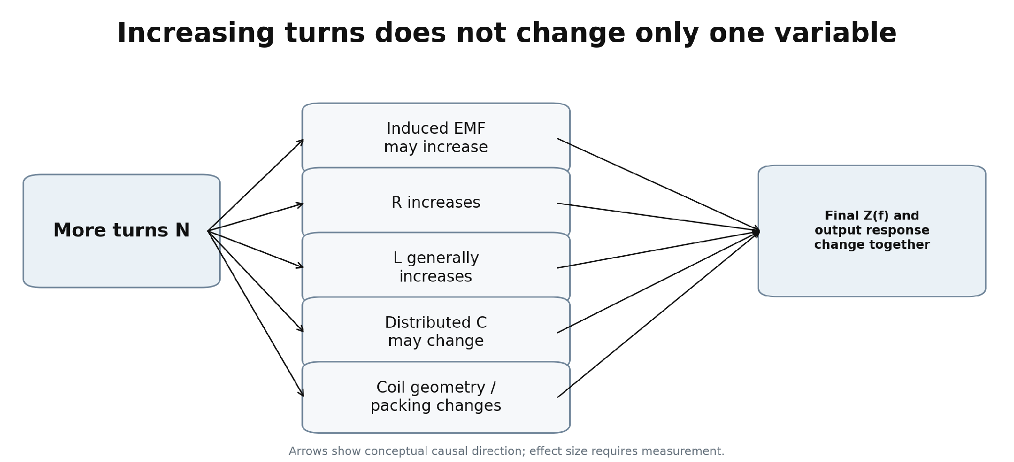
Figure 3. Causal map showing how added turns alter several electrical and geometric variables at once.
Qualitative RavenForge working model. Effect sizes require measurement for each pickup architecture.
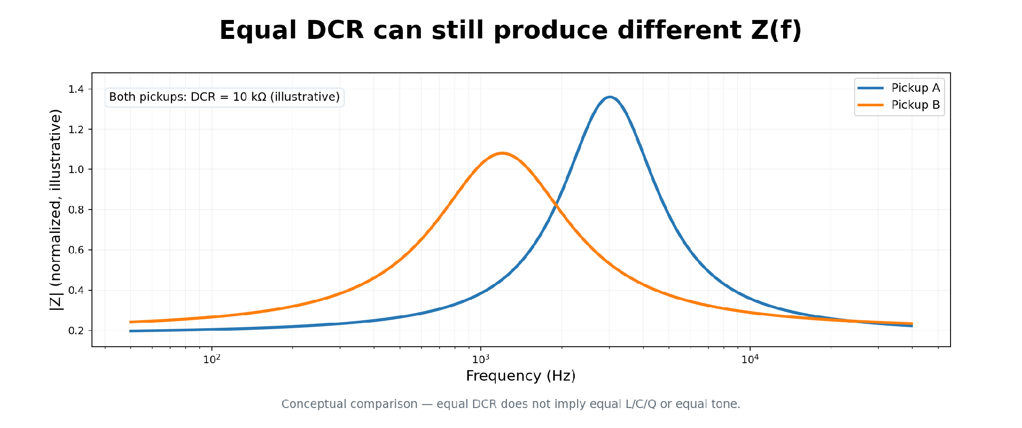
Figure 4. Why equal DCR does not guarantee equal frequency-dependent impedance.
Illustrative curves. A single “10 kΩ” value does not determine L/C/Q or the actual transfer response.
7. Magnetic circuit, metal parts and eddy-current loss
Rather than translating magnet names directly into adjectives such as warm, bright or aggressive, A03 separates their causal routes. Permanent-magnet flux and string coupling primarily affect the source term, while permeability and conductivity of poles, blades, cores, steel hardware, baseplates and covers can alter L(f), loss and Q [2,5].
Lemme’s technical measurements report commercial pickup examples in which the presence or absence of a metal casing changes resonance/Q [4]. The engineering implication is to record conductivity, permeability, thickness, geometry and electrical continuity and then measure Z(f), rather than memorizing a tone adjective by material name. Nickel silver cannot be assumed to be perfectly “electrically transparent.”
8. Z(f) versus H(f) — an impedance test is not an output test
Complex terminal impedance Z(f) is a network property obtained by electrically probing the pickup terminals. Magnetic-excitation→output transfer Hmag→V(f), by contrast, describes how an external magnetic perturbation becomes output voltage. The curves are related but they are not the same physical quantity.
Horton/Moore and Lemarquand illuminate source geometry and nonlinearity [1,2], while Lemme describes a practical pickup-analyser method that excites the pickup with a transmitting coil rather than a moving string [4]. RavenForge should therefore record Z(f) sweeps and H(f) measurements as separate channels.
Measurement boundary Impedance peak ≠ output peak. Z(f) asks “how does the pickup look electrically?”; H(f) asks “how does magnetic excitation become voltage?” |
9. Active pickups are a separate architecture class
Powered pickups such as EMG and Fishman Fluence combine an internal transducer with active electronics that shape output impedance and voice/transfer behavior. The EMG 40-TW-X official sheet specifies 2 kΩ output impedance, while Fishman Fluence Bass Soapbar specifies 9.4 kΩ output impedance and current draw [9,10]. These are complete-output architecture values, not equivalents of passive-coil DCR/L/C.
Passive high-impedance pickups and powered/active pickups should therefore not be ranked on one DCR–L–C–Q scale. Shared comparison should instead use architecture class, transduction topology, output/source impedance, transfer behavior, required interface/load, noise, and headroom/current where applicable.
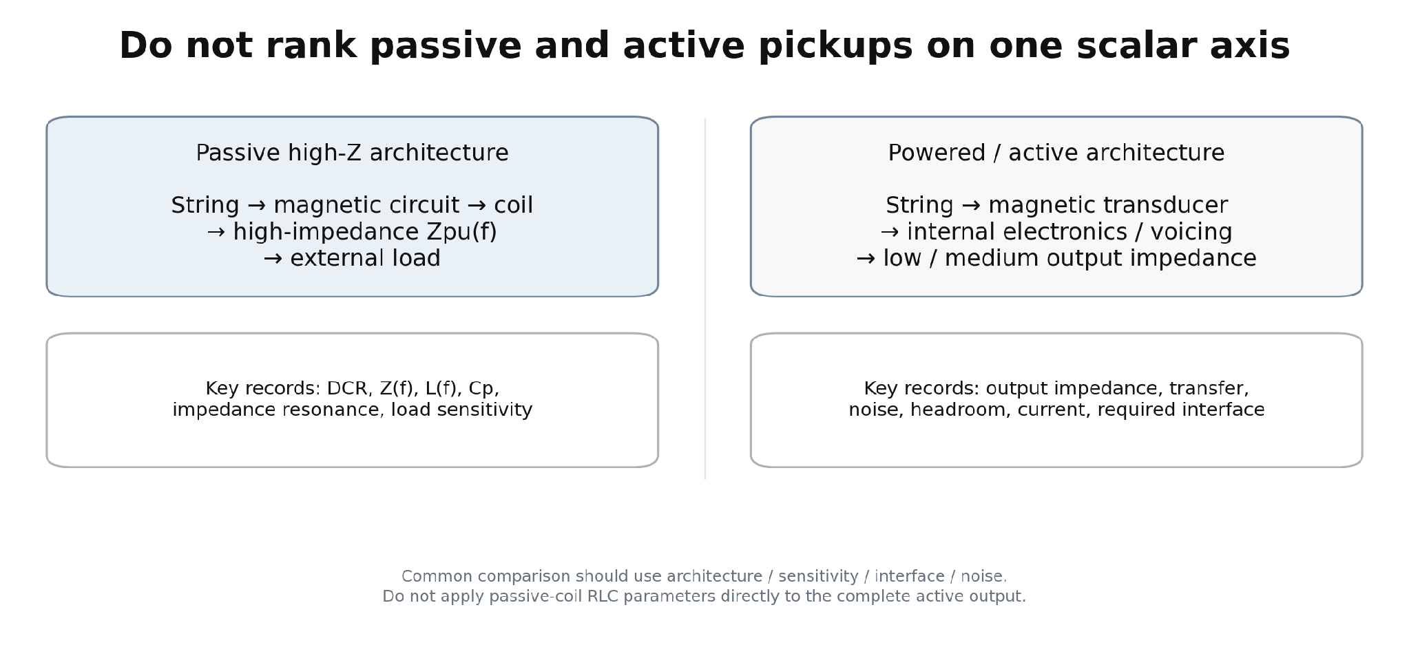
Figure 5. Architecture boundary between passive high-Z and powered/active pickups.
Shared functions can be compared, but passive-coil RLC metrics are not applied directly to the complete active output.
10. Evidence matrix — what can A03 legitimately claim?
Claim | Assessment | RavenForge wording |
Higher DCR means higher output | Correct but conditional | Only a useful turns/length proxy inside a controlled family; not a universal cross-brand rule |
Higher DCR means darker/warmer | Unsupported as a standalone rule | L/C/Q/source/load jointly matter |
Higher inductance is always darker | Too strong / conditional | resonance and damping also depend on C, losses and load |
More turns only increase output | Incorrect | R/L/C/geometry and transduction sensitivity change together |
Scatter winding lowers C and sounds more open | Plausible, requires measurement | physically plausible but controlled pickup-specific evidence is weak |
AWG43 is inherently hotter than AWG42 | Unsupported standalone claim | cannot be separated from resistance, packing and turn count |
One resonant frequency predicts tone | Too strong | Q, transfer sensitivity, spatial sampling and loading are also required |
A passive pickup is an RLC circuit | Correct only as first-order equivalent model | distributed winding, losses and source physics are simplified |
Active pickups can be directly compared with passive RLC metrics | Incorrect / architecture-dependent | the complete output architecture is different |
A 500k pot changes the pickup’s intrinsic R/L/C | Move to A04 / needs correction | it changes loaded system response rather than intrinsic coil parameters |
Impedance peak equals actual output peak | Incorrect simplification | Z(f) and Hmag→V(f) are different quantities |
Higher Q means a better pickup | Incorrect | Q is a damping descriptor, not a quality score |
A metal cover always cuts treble | Too strong | effect size depends on conductivity, permeability and geometry |
Nickel-silver covers are electrically transparent | Unsupported absolute claim | lower loss is not the same as zero interaction |
11. RavenForge Pickup Characterization Protocol
The purpose of A03 is not to accumulate more spec-sheet numbers but to establish a common measurable language. Bench testing should avoid the absolute word “unloaded” and instead state the fixture input impedance/capacitance as a specified high-impedance condition. Perfect zero loading does not exist; lead and fixture parasitics are part of the measurement system.
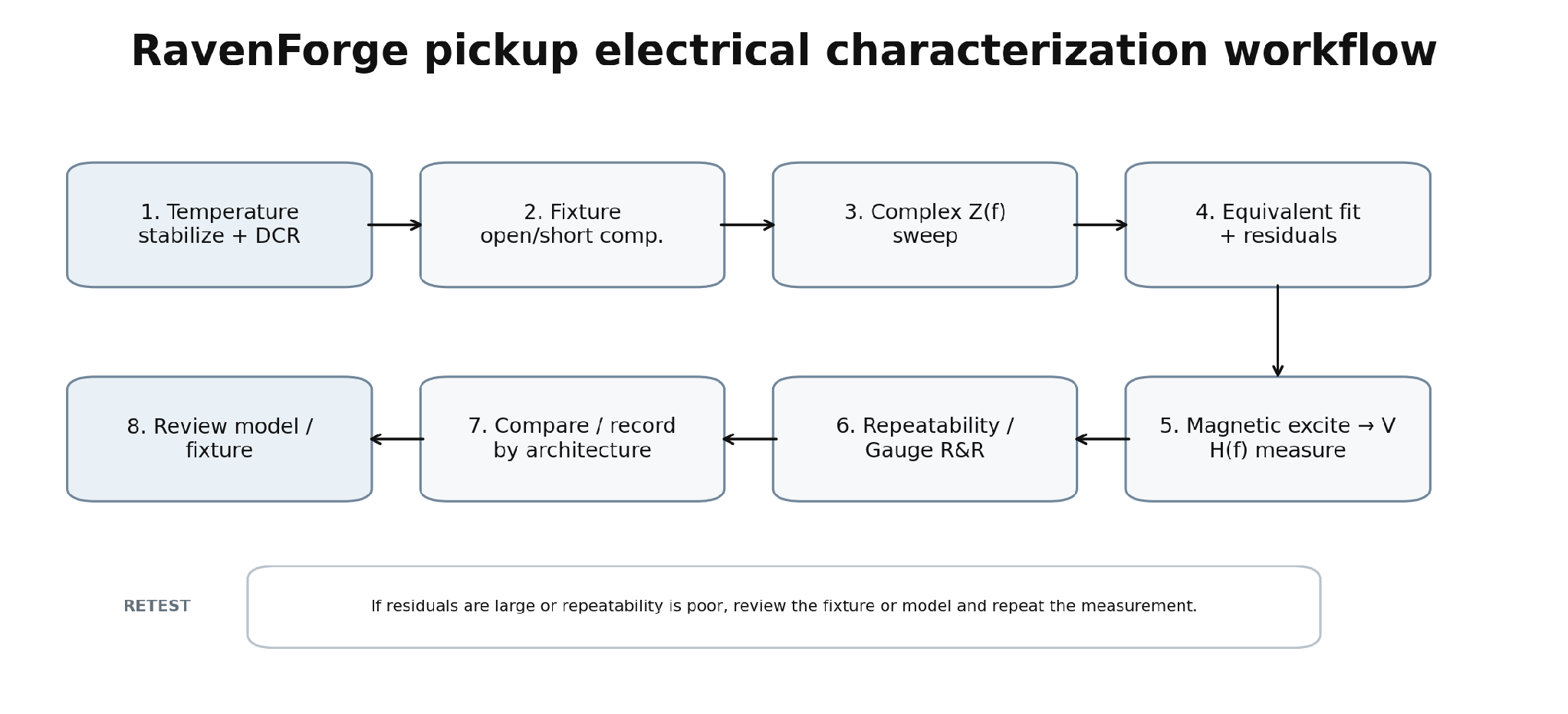
Figure 6. RavenForge pickup electrical & transfer characterization workflow.
Z(f) and H(f) are measured as separate channels while fixture compensation, fit residuals and repeatability are preserved.
Stage | Record / condition | Decision |
Temperature stabilize | pickup, fixture and meter temperature; allow thermal equilibrium | DCR comparability |
DCR | 4-wire/compensated method when practical; record °C and lead condition | winding descriptor |
Fixture compensation | open/short; known reference where available; fixed lead length and shielding | remove fixture parasitics |
Complex Z(f) | magnitude + phase sweep; stated excitation level and range | primary electrical data |
Model fit | fit R/L/C or extended network; store residuals and validity band | compact descriptor, not replacement data |
Magnetic H(f) | controlled excitation coil or moving-string fixture; fixed geometry | transduction response |
Hardware state | cover/baseplate/poles/string proximity/orientation recorded | reproducibility |
Repeatability | re-seat pickup; repeated sweep; Gauge R&R | measurement uncertainty |
Archive | raw complex data, calibration, instrument settings, photos | traceable dataset |
12. RavenForge comparison frame — placing Delano / Turner / Herrick / Nova beside EMG / Fishman
Field | Passive high-Z class | Powered / active class |
Architecture | coil topology / hum-cancel / multicoil state | transducer + internal electronics / voice topology |
DCR | record @ temperature | not a direct whole-system comparison metric |
Complex Z(f) | core metric | output Z(f) may be relevant, but not equivalent to passive coil Z(f) |
L(f), Cp, impedance resonance | characterization metrics | usually internal/transducer-level only |
Magnetic→V transfer | core metric | core metric at complete output |
Output/source impedance | frequency-dependent, often high | manufacturer/measurement value |
Required interface/load | A04 | manufacturer/interface requirement |
Noise | measure | measure |
Headroom / current / power | normally N/A | required where applicable |
Wiring state | each series/parallel/coil state measured separately | each voice/mode documented separately |
13. A03 / A04 / A05 / C-log boundary
Code | Scope |
A03 | pickup equivalent impedance, DCR, Z(f), L/C/Q/loss, winding/magnetic/metal-part influence |
A04 | 250k/500k/1M pots, cable capacitance, amplifier/input impedance and loaded response |
A05 | high-Z buffer input, low-Z output, cable isolation and active interface |
C03 proposed | actual pickup DCR + complex Z(f) + magnetic transfer H(f) characterization and Gauge R&R |
14. Current conclusion — expand pickup specification from “one kΩ number” to a frequency-dependent system
A03 establishes the RavenForge minimum description as `architecture + source mechanism + complex Z(f) + measurement condition + magnetic transfer H(f)`, not DCR alone. R/L/C are useful first-order descriptors but do not replace distributed winding or loss mechanisms.
Accordingly, “higher DCR,” “larger inductance,” or “higher Q” are not independent quality rankings. Model voice starts with the B02 Sonic Brief, then A02 pickup coordinate, A03 pickup electrical architecture, A04 load and A05 interface are separated and recombined through prototype data.
Current design position A pickup earns its place through measured and validated system behaviour, not through DCR, magnet material, wire gauge or boutique winding lore taken in isolation. |
15. Next research — variables passed to A04
Code | Research question | Variables / purpose |
A04 | Electrical Loading of Passive Pickups | 250k / 500k / 1M pots, cable capacitance, input impedance, loaded resonance and Q |
C01 | Pickup Position FFT Mapping | A02 spatial-sampling validation |
A05 | Active Buffers and Input Impedance | high-Z sensing, low-Z drive and cable isolation |
C03 proposed | Pickup Electrical & Transfer Characterization | DCR, Z(f), H(f), covers/baseplates and repeatability |
References
[1] Horton, N. G.; Moore, T. R. “Modeling the magnetic pickup of an electric guitar.” American Journal of Physics 77(2), 144–150 (2009). DOI: 10.1119/1.2990663.
[2] Lemarquand, G.; Lemarquand, V. “Calculation Method of Permanent-Magnet Pickups for Electric Guitars.” IEEE Transactions on Magnetics 43(9), 3573–3578 (2007). DOI: 10.1109/TMAG.2007.891671.
[3] Paiva, R. C. D.; Pakarinen, J.; Välimäki, V. “Acoustics and Modeling of Pickups.” Journal of the Audio Engineering Society 60(10), 768–782 (2012).
[4] Lemme, H. E. W. “The Secrets of Electric Guitar Pickups.” Technical article / guitar-electronics reference; updated 2026. Includes first-order pickup electrical models, measurement methods and resonance tables.
[5] Zollner, M. Physik des Magnettonabnehmers. Selbstverlag, Regensburg (2022), 287 pp. Technical monograph; pickup impedance, loss and equivalent-network treatment.
[6] Matula, R. A. “Electrical resistivity of copper, gold, palladium, and silver.” Journal of Physical and Chemical Reference Data 8(4), 1147–1298 (1979). DOI: 10.1063/1.555614.
[7] U.S. Bureau of Standards. Circular No. 31, Copper Wire Tables, 3rd ed. Resistance conversion at 20 °C and temperature coefficient ≈ 0.00393 K⁻¹ for standard copper wire calculations.
[8] Batchelor, C.; Gooding, J.; Marriott, W.; Chalashkanov, N.; Tucker, N.; Margetts, R. “Guitar Pickups I: Analysis of the Effect of Winding and Wire Gauge on Single Coil Electric Guitar Pickups.” arXiv:2409.19782 (2024). Preprint; peer-review status not verified.
[9] EMG Pickups. 40-TW-X installation/specification sheet, model 40-TW-X. Official manufacturer documentation; output impedance 2 kΩ for cited modes.
[10] Fishman. Fluence Bass Soapbar 5-String Pickups official specifications. Output impedance 9.4 kΩ; current draw and voice peak-frequency data for the cited model.
[R1] RavenForge / Signal & Transduction Research Log A01. “From Mechanical Vibration to Electrical Signal.” 2026.09.05.
[R2] RavenForge / Signal & Transduction Research Log A02. “Pickup Position and Harmonic Sampling.” Verified revision, 2026.09.06.
[R3] RavenForge / Design Methodology Research Log B02. “Voicing Before Specification.” 2026.09.08.
Source status and interpretive boundary [1–3,6] are peer-reviewed or reference-quality academic sources. [4] Lemme and [5] Zollner are authoritative guitar-electronics technical literature/monographs but are kept distinct from peer-reviewed journal papers. [8] is a controlled-winding preprint whose peer-review status is not verified, so it is used only as limited evidence. [9–10] are manufacturer documents used only to confirm the architecture/specifications of the cited active models. The RavenForge measurement protocol, comparison schema and proposed C03 are internal engineering frameworks derived from these sources. |
Working research document · 2026.09.09