RAVENFORGE / PROTOTYPE DEVELOPMENT LOG

RAVENFORGE
Prototype Development Log
From Concept to Buildable Geometry
Superstrat / ASKR / EMBLA — CAD Iterations, Failure Cases, and Design Lessons
Purpose of This Document Rather than simply presenting the final drawings, this log documents which assumptions proved incorrect and how they were corrected through verification during the process of developing buildable geometry. The core of this development log is to preserve failed revisions and discarded designs as part of the design rationale, without concealing them. |
Projects | 24-Fret Superstrat / ASKR 37–34" Multiscale Bass / EMBLA 34" Bass |
Focus | Hardware reference points, neck joint, routing, battery/electronics packaging, string path, DXF integrity |
Evidence | CAD previews and clearance check images generated during the project |
Status | Prototype drawings undergoing iterative validation |
1. What This Research Log Documents
When I first drew the initial sketches, the first things that stood out were the exterior shapes of the body and headstock. However, as I repeatedly revised the production drawings, the priorities completely shifted. Before finalizing the instrument’s silhouette, I had to establish the scale, nut, fret positions, functional reference points for the bridge, string path, neck joint, and routing envelope.
The three projects varied in difficulty. With the 24-fret Superstrat, I mastered the basic rules of CAD and production drawings; with the ASKR, I encountered issues where changing a single part had a cascading effect on the entire geometry due to the 37–34-inch multiscale design and complex electronics. For the EMBLA, while using a more traditional 34-inch platform, I had to integrate the headstock, neck feel, and option compatibility into a single design framework.
Key Perspective A drawing is not an illustration. It is a system of dependent geometry. |
2. Superstrat — Reorganizing the Design Process While Learning CAD
The first production drawing was for a Superstrat based on a 25.5-inch scale, 24 frets, a 6-inline headstock, and a Gotoh 510-series tremolo with an HSH pickup configuration. Initially, I approached the design by placing the exterior shape and component images, but as I began comparing the actual hardware measurements with the front and back views, it repeatedly became clear that even if the drawing looked correct, it could still be incorrect by manufacturing standards.
2.1 Tuners: The Posts and Screws, Not the “Shape,” Were the Criteria
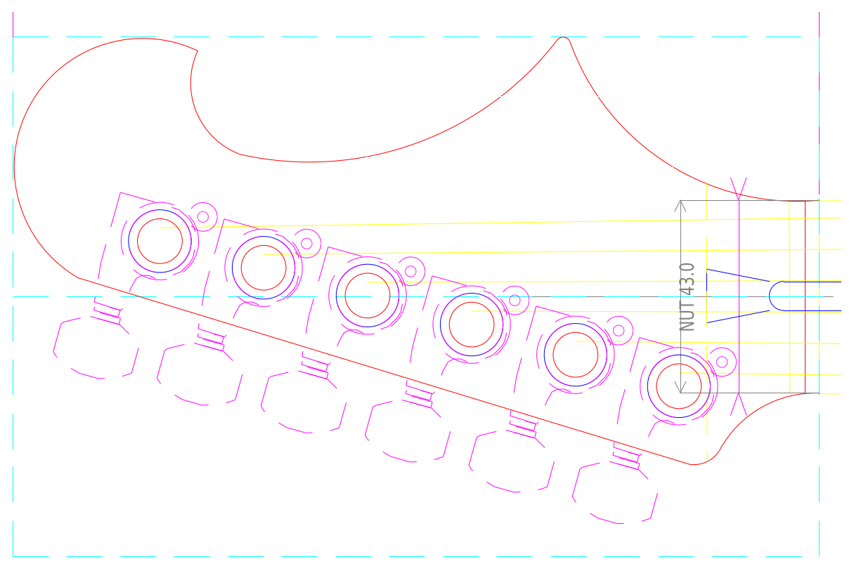
The initial layout for the SG381-07 MGT began by projecting the hardware shapes onto the front and rear views. At this stage, the tuner’s exterior shape and the orientation of the buttons were clearly visible, but the post center, fixing screw center, and the left-right reversal of the rear housing—which were actually critical—were not sufficiently controlled.
Figure 1. Initial headstock projection design. A stage where attempts to align the front and rear views simultaneously led to unclear reference points for the housing and fixing screw orientations.
Failure Case 01 If the tuner geometry that appears correct from the front is copied exactly to the rear, the left and right sides will be reversed in the actual back view. Even if a single fixing screw position is off, it is difficult to correct during the wood drilling stage. |
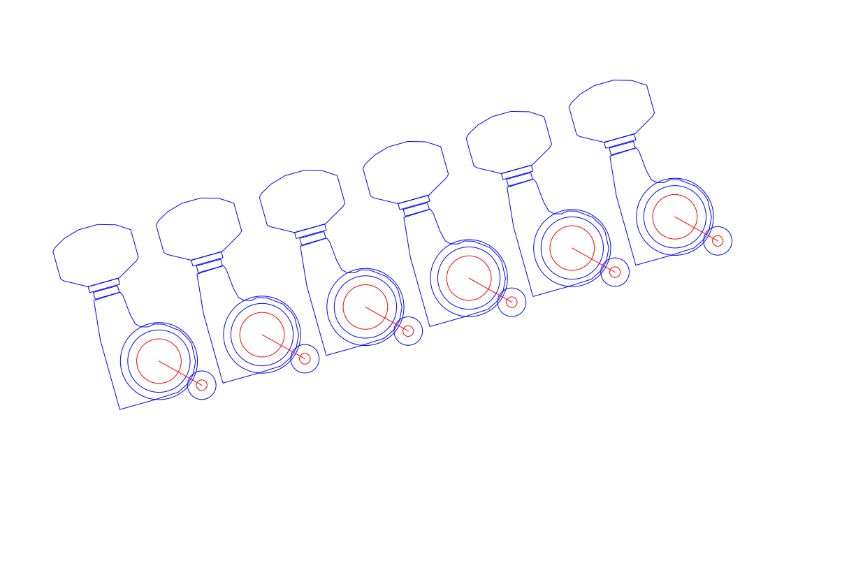
Instead of trying to “neatly” align the front and rear views as separate drawings, I reorganized the design so that they share the same post center and only the rear housing is mirrored to match the view’s reference.
Figure 2. REV-G Front Head: Re-verifying post positions based on the nut and current reference line. RavenForge_Superstrat_24F_REV-G_FRONT_HEAD_PREVIEW.png | Figure 3. REV-G Rear Head: Separate verification of the rear housing and fixing screw orientation based on the same post. RavenForge_Superstrat_24F_REV-G_REAR_HEAD_PREVIEW.png |
Design Rule The front and rear drawings are not separate drawings. They are two views of the same geometry. |
2.2 The deep tenon and front pickup required the same space
While reviewing a deep-tenon-style structure to position the front pickup as close as possible to the edge of the fingerboard and simultaneously increase the neck’s joint area, a spatial conflict arose. We wanted the neck wood to extend all the way under the pickup, but routing the pickup required removing that same area.
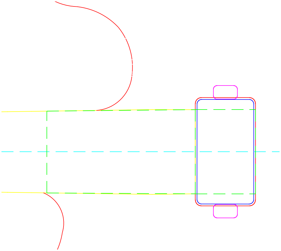
Figure 4. Review of the boundary between the front pickup and the neck pocket/tenon. As the pickup is moved forward, the effective length of the neck wood decreases.
RavenForge_Superstrat_24F_REV-N_front_tenon_detail.png
Failure Case 02 It was not possible to simultaneously maximize the two goals of “making the neck stronger by inserting it deeper” and “moving the neck pickup forward.” Consequently, the tenon length, pickup routing depth, and the remaining wood thickness in that section had to be considered together. |
2.3 Clearance and load paths were more important than the number of bolts
We also considered increasing the number of bolts to reinforce the neck joint, but due to the rear tremolo cavity, spring clamps, and front pickup routing, areas that appeared to be “empty space” were often actually unusable. The clearance check below is a verification step where the bolt arrangement and the neck-pocket envelope were overlaid separately.
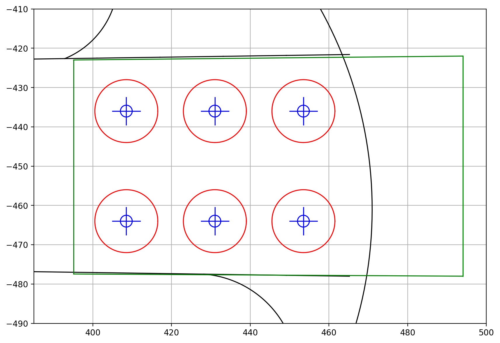
Figure 5. Rear clearance check. A stage in which the body/neck-pocket boundary and machining allowance were verified first, rather than the 6-bolt arrangement itself.
REV-J_rear_clearance_check.png
Design rule More fasteners do not automatically result in a better joint. It is necessary to consider the locations where clamping force is required, the remaining wood thickness, and the presence of a cavity on the opposite side. |
2.4 If the file won’t open, it’s not a drawing—even if the geometry is correct
During Superstrat work, we repeatedly encountered issues where not only geometry errors but also the DXF structure itself was rejected by AutoCAD. In one instance, a group code not allowed in an R12 table caused the entire drawing to be discarded; later, we also encountered issues with duplicate handles and entity class separators.
Unknown group 74 for table on line 72 |
Subsequently, prioritizing compatibility, we conservatively revised our file creation rules to adhere to the AutoCAD R12 ASCII structure, use simple LINE/CIRCLE/TEXT entities, perform explicit layer registration, and remove unnecessary handles and polylines.
Design Rule Production drawings require two types of accuracy: geometric correctness and file integrity. |
3. ASKR — Multiscale Reveals Dependencies Between Parts
The ASKR was designed with a 37–34-inch 5-string multiscale, bridge-mounted pickups, an 18V electrical system, and expansion options in mind. Problems that were resolved around the centerline in the Superstrat became intertwined in the ASKR, involving each string’s scale line, pickup angle, bridge segment, string path, control cavity, and even battery packaging.
In particular, although the battery box appeared to be a small component, it was one of the elements that required the most repositioning. This was because it had to avoid the neck pocket, body contour, tummy cut, control cavity, and the future 3-pickup keep-out area.
3.1 As soon as we added 3-pickup expandability, the battery location became an issue again
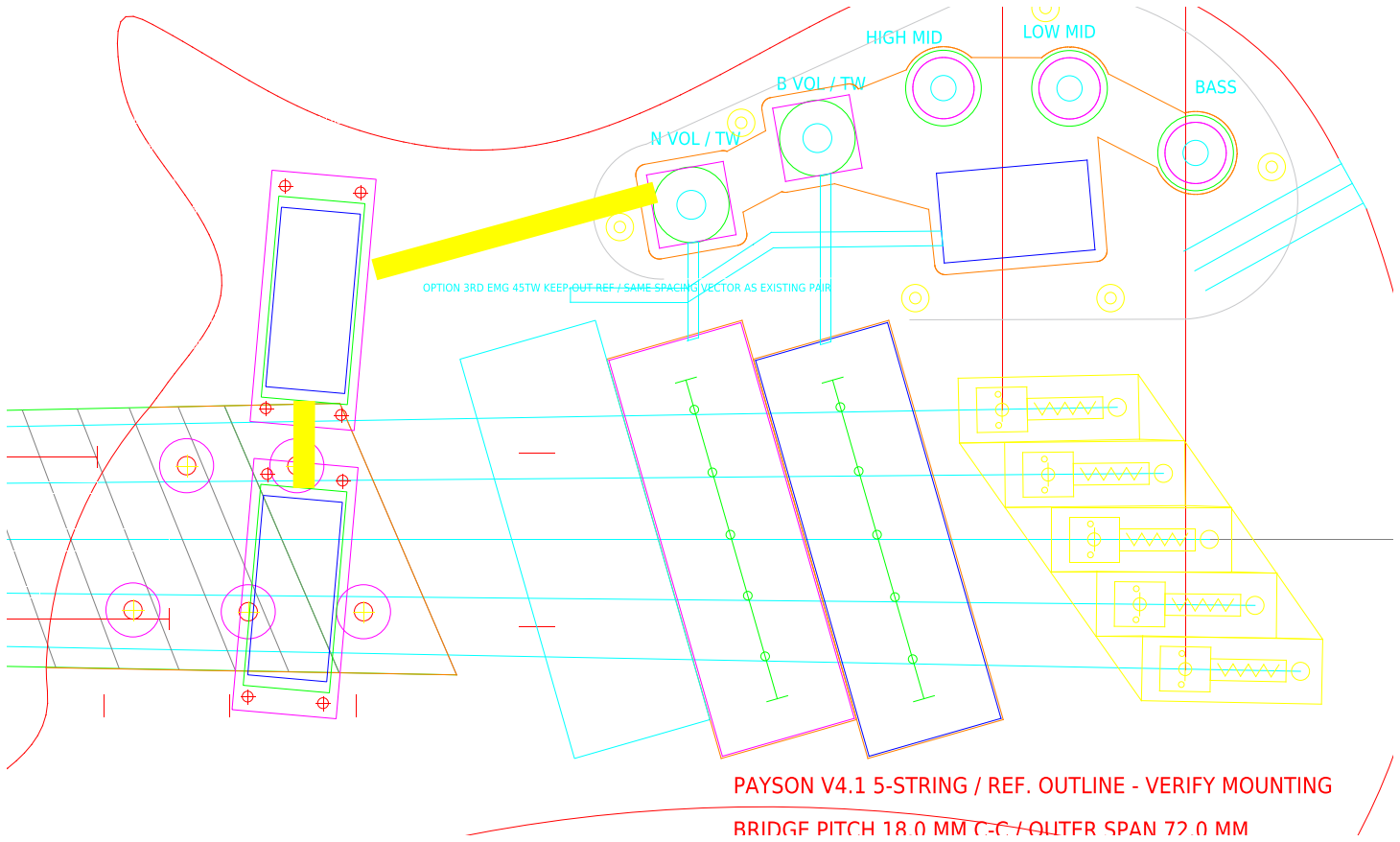
Figure 6. Front view review after adding the 3rd pickup keep-out. It became clear that independent placement of the battery, bolts, pickups, and bridge was impossible.
RavenForge_ASKR_REV_AF_front_battery_3pickup_keepout.png
Failure Case 03 The space that was available when assuming only a 2-pickup configuration disappeared the moment the 3-pickup template was applied. The approach of adding options later ultimately forced us to redesign the existing routing and battery placement. |
3.2 Every time the BB-04W was repositioned, a different problem arose
Moving the battery box closer to the center of the body caused conflicts with the neck/heel and wiring, while moving it toward the outer edge encroached on the belly/tummy contour and the body outline. The image below shows the steps leading to a layout that was ultimately discarded.
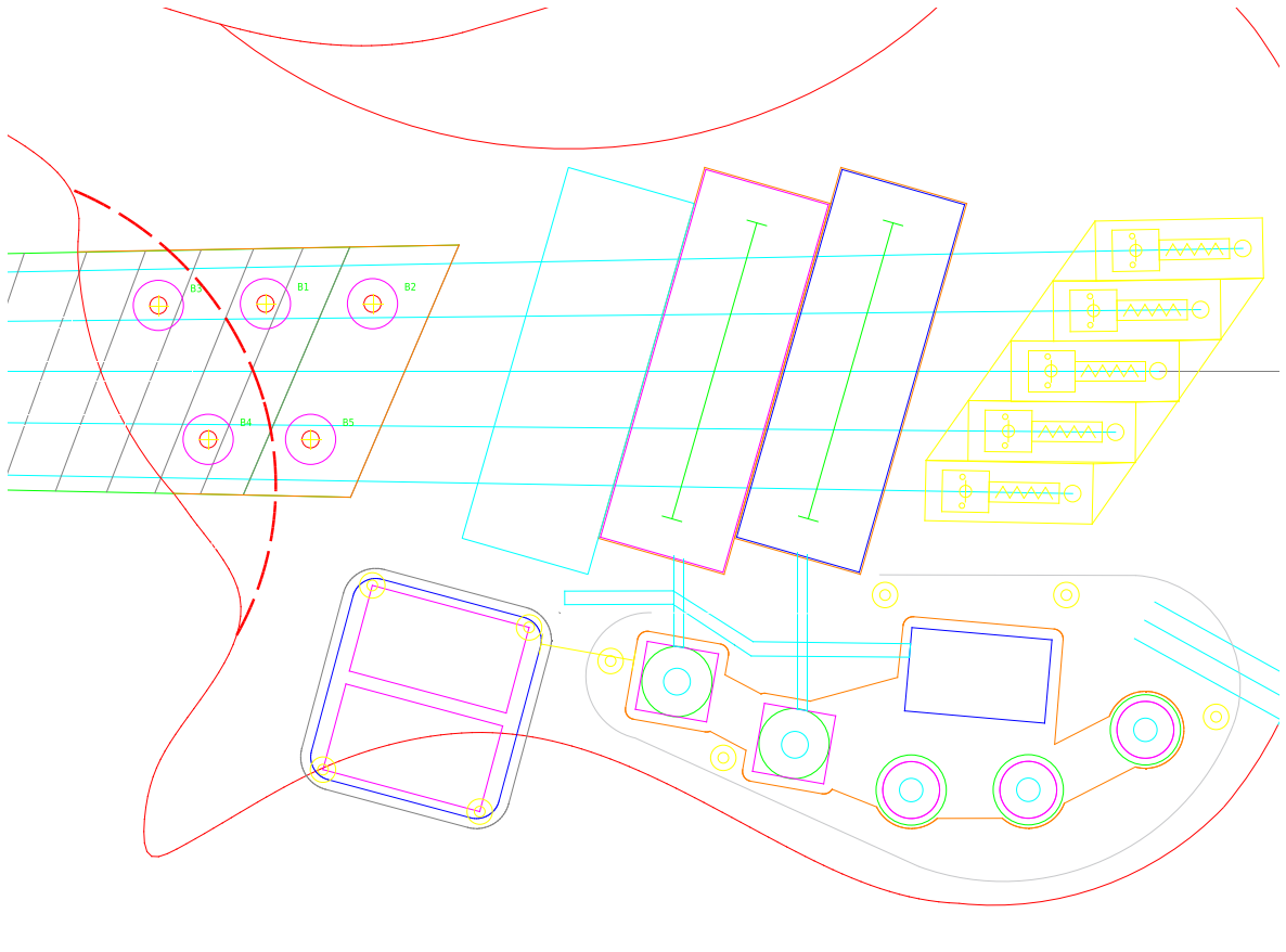
Figure 7. REV-AH. A layout where the battery box is too close to the lower/waist contour envelope, resulting in insufficient machining clearance.
RavenForge_ASKR_REV_AH_rear_BB04W.png
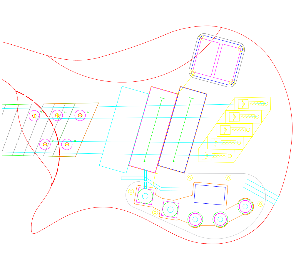
Figure 8. REV-AI. A discarded design where the box was moved to the lower bout, but the clearance between the box’s outer edge and the body contour remained unstable.
RavenForge_ASKR_REV_AI_rear_BB04W_lower_bout.png
Failure Case 04 It was not sufficient that the box “appeared to fit” inside the body outline on the screen. A safety margin was required that accounted for the actual rear contour depth, screw flange, router access, and wiring bore. |
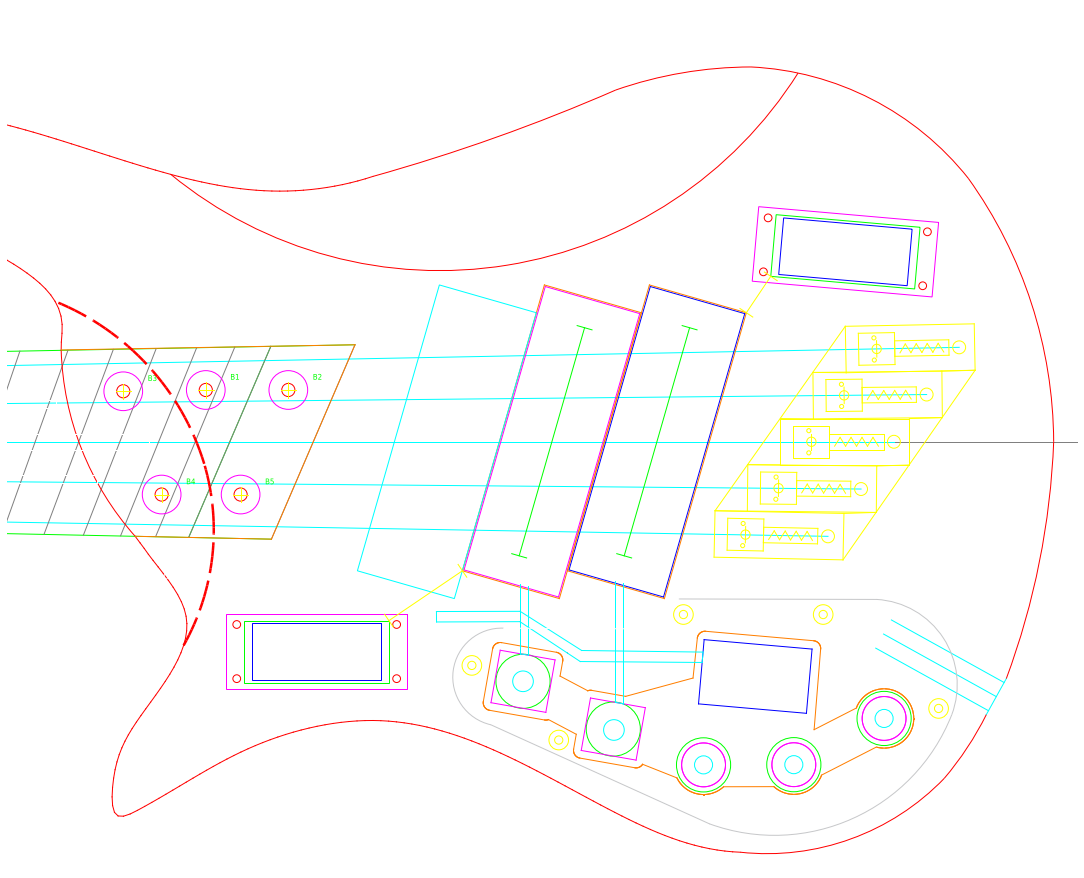
Figure 9. REV-AJ. A relatively stable candidate design in which the components have been separated and repositioned to avoid the tummy contour.
RavenForge_ASKR_REV_AJ_rear_split_BB04_tummy_safe.png
Design Rule Electronics are mechanical packaging. Even components that can be connected on a circuit diagram occupy actual volume and machining allowance within the body. |
3.3 The headstock also had to be included within the housing envelope
The headstock design wasn’t complete just by aligning the post holes. When we incorporated the HB6 series and added the actual physical envelopes of the rear housing and the key, the clearances between the headstock perimeter, the adjacent tuners, and the string path changed again.
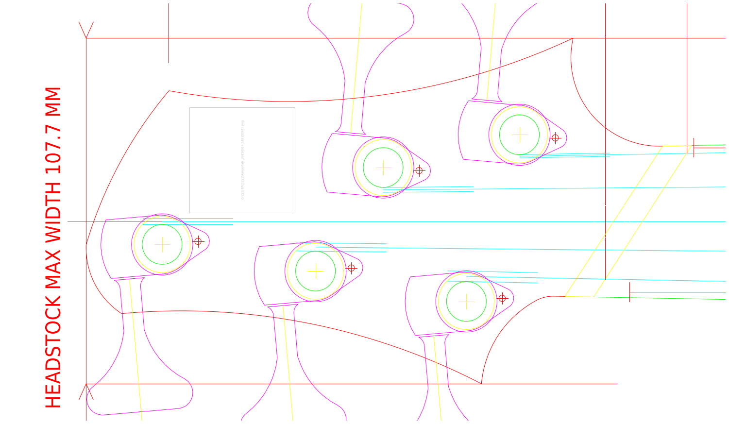
Figure 10. HB6Y housing-safe review. This stage involves positioning not only the post center but also the actual housing envelope and string path together.
RavenForge_ASKR_REV_HB6Y_front_head_housing_safe.png
Design Rule Hardware change = geometry change. Replacing tuners or the bridge doesn’t just change the drill holes; the surrounding contours and string path must also be re-verified. |
4. EMBLA — Even the “traditional 34-inch” model was not simple
Although EMBLA is a more traditional 34-inch 5-string platform than the ASKR, a different kind of trial and error arose in the process of simultaneously achieving the desired playing feel, headstock design, physical hardware, and expandability options. In particular, even when using a specific brand’s neck feel as a reference, the dimensions could not be copied directly if the number of frets, heel width, fingerboard radius, or joint method differed.
4.1 We had to map out the nut-to-post string path first
Initially, we focused on whether the tuners were balanced within the headstock’s outer perimeter. However, in practice, the priority was determining the angle at which each string traveled from the nut witness point to the post center. The thick B and E strings could not be treated with the same aesthetic symmetry as the thin D and G strings.
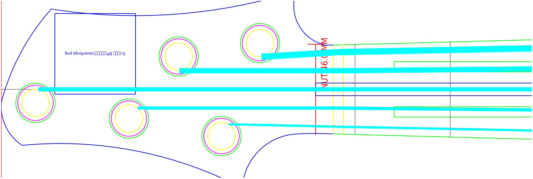
Figure 11. REV-I nut/string study. The actual nut-to-post path is highlighted with a cyan line to re-examine the straight pull and post placement.
RavenForge_EMBLA_002_REV_I_nut_strings.png
Failure Case 05 If the head outline is fixed first, the post ends up being forced into place. Subsequently, the priority order was changed to: nut slot → string path → post center → housing → head outline. |
4.2 Tuner Bank Orientation and Rear-View Mirror Issue
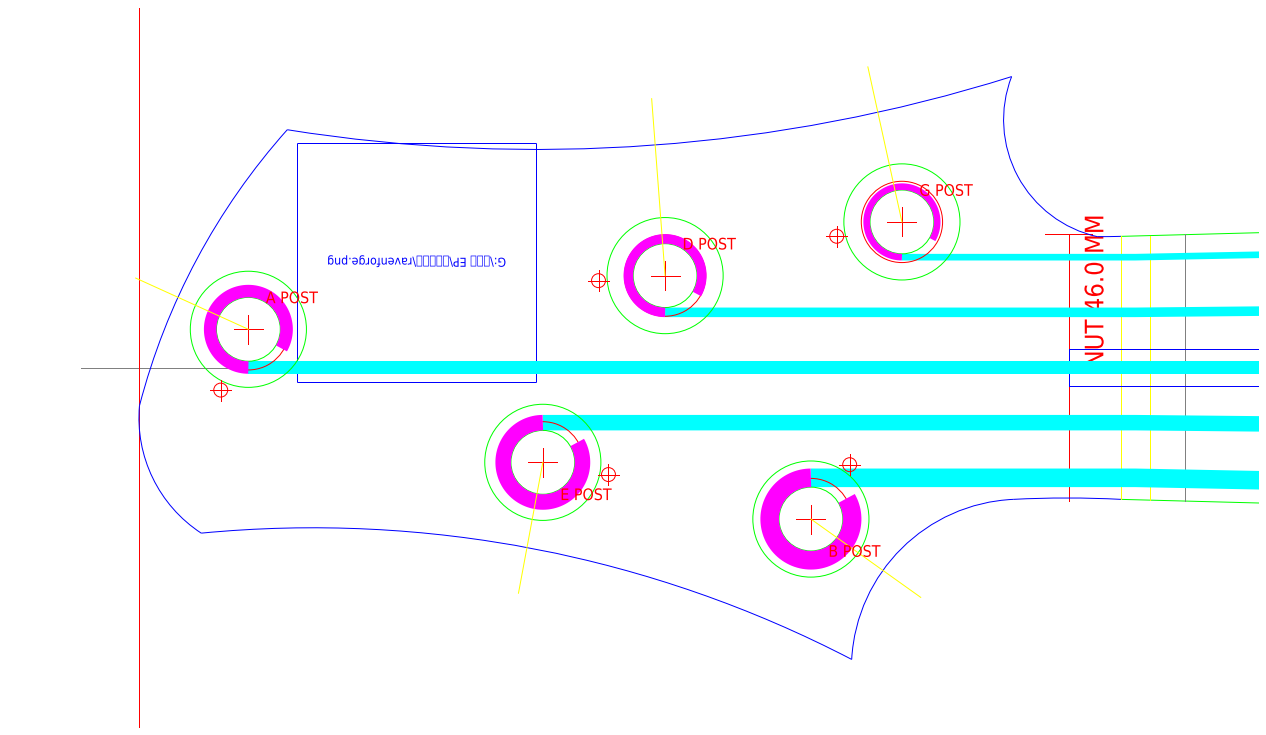
Figure 12. REV-K. The stage where the geometry of each post and string line was recreated. Since some reference geometry was flipped, the bank orientation was reworked in a subsequent revision.
RavenForge_EMBLA_002_REV_K_head_tuner_geometry.png
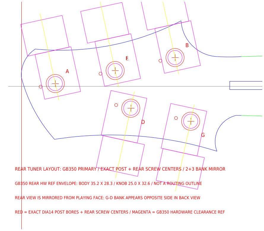
Figure 13. REV-M rear tuner layout. We specified the “mirror rule” stating that the 2+3 bank, as seen from the playing face, appears on the opposite side in the rear view.
RavenForge_EMBLA_002_REV_M_rear_tuners.png
Design Rule Reference ≠ specification. A reference is a tool for describing the intended feel and proportions; actual manufacturing dimensions must be recalculated to match the scale, fret count, heel, and hardware of the current instrument. |
5. Recurring Patterns of Failure Across Three Projects
Although the projects differed, the causes of failure were surprisingly consistent. Most began with the assumption that “if I put parts that fit independently into a single instrument, the whole thing will fit.” In reality, the position of a single part required changes to the surrounding machining, the structure on the opposite side, and even the work sequence.
Case | Symptoms | Cause | Corrective Action | Remaining Principles |
Head Tuner Mirror | Front/rear screw direction mismatch | Manage the view as shown in the separate diagram | Common post center + rear mirror | Front/rear = same geometry |
Deep tenon vs. pickup | Front pickup and neck wood conflict | Both components occupy the same space | Simultaneous review of tenon, routing, and depth | More is not always stronger |
Rear bolt clearance | Interference between cavity and edge when adding bolts | Thinking in terms of the number of bolts | Prioritize load location and remaining wood | Position > count |
DXF integrity | Drawing discarded in AutoCAD | Incompatible entity/table/handle | Reduced to a simple R12 structure | File integrity is design quality |
ASKR battery | Box encroaches on contour/keep-out | Treating electronic components as 2D symbols | Physical envelope + routing margin | Electronics = packaging |
3PU option | Existing 2PU layout collapses upon expansion | Add the option as a lower priority | Set compatibility keep-out early on | Modularity creates constraints |
EMBLA string path | Discrepancy between the desired head layout and the current path | Periphery-first design | Prioritize nut-to-post | Function before silhouette |
6. Reasons for Separating Production Drawings and Work Templates
Initially, we attempted to include all information in a single master drawing. However, router templates do not require wiring plans, and head templates do not require information on the rear control cavity. A drawing is not necessarily better simply because it contains more information; a drawing that retains only the information necessary for each work stage is safer.
- Master Drawing — Manages overall reference geometry and relationships between parts
- Neck / Head Template — Focus on outline, nut, tuners, and truss/reinforcement centers
- Body Routing Template — Focus on the neck pocket, pickup routing, and bridge reference
- Rear Template — Focus on the cavity, tremolo/spring, or battery route
- Pickguard Template — Retains only the actual cutting outline and openings
- 1:1 Print Template — Verify print scale, tile overlap, and crop marks separately
Design Rule A good production drawing does not contain the most information. It contains the right information for the operation being performed. |
7. Current Conclusion — A drawing is a hypothesis, not an answer
Even if all interferences are eliminated in CAD, it cannot be assumed that actual production will be successful. Variations in wood, tolerances of router bits and jigs, manufacturing deviations in hardware, and assembly accessibility can only be verified on an actual prototype. Therefore, the current drawing is not the final answer but rather the most refined hypothesis established prior to production.
Prototype Loop CAD iteration → 1:1 template → physical prototype → measurement → revision |
In the next verification phase, we measure the actual neck-pocket fit, bridge/string alignment, tuner clearance, reinforcement operating range, pickup routing depth, cavity wall thickness, battery accessibility, center of gravity, and workability, and incorporate these findings into the drawing revision.
“The drawing is not the instrument.
It is a hypothesis about the instrument.
The prototype is the experiment.”
Working Research Document · August 30, 2026