RAVENFORGE / SIGNAL & TRANSDUCTION RESEARCH LOG — A01
RAVENFORGE
Signal & Transduction Research Log
A01 — From Mechanical Vibration to Electrical Signal
From string–structure coupling to magnetic transduction and electrical output
문서 목적 |
Code | A01 |
Focus | String vibration · mechanical coupling · pickup spatial sampling · magnetic transduction · electrical boundary |
Evidence | Musical acoustics · JASA / JAES / IEEE pickup studies · controlled electric-guitar experiments |
RavenForge link | material → vibration → pickup → output signal model |
Downstream logs | A02 / A03 / A04 / C01 / C02 / A05 |
Status | Literature framework established · prototype validation pending |
1. 연구 질문 — 전기악기의 신호는 어디에서 시작되고 어디에서 바뀌는가
전기 기타와 베이스의 최종 출력은 어느 한 부품이 독립적으로 생성한 결과가 아니다. 연주자가 현에 초기 변위와 속도를 부여하면 현은 장력·길이·선밀도·강성의 조건 아래 진동하고, nut/fret 및 bridge에서 neck/body 구조와 에너지를 교환한다. 그 결과 만들어진 현 운동 중 픽업이 위치한 공간의 성분이 magnetic circuit을 변화시키고, coil에 유도전압이 발생한다. 이후 pickup impedance와 control/cable/input loading이 다시 frequency response를 바꾼다 [1–7].
핵심 관점 |
Figure 1. A01에서 정의하는 RavenForge signal chain. RavenForge schematic · literature framework based on Fletcher & Rossing, Paté et al., Horton & Moore, Paiva et al. [1–6]. |
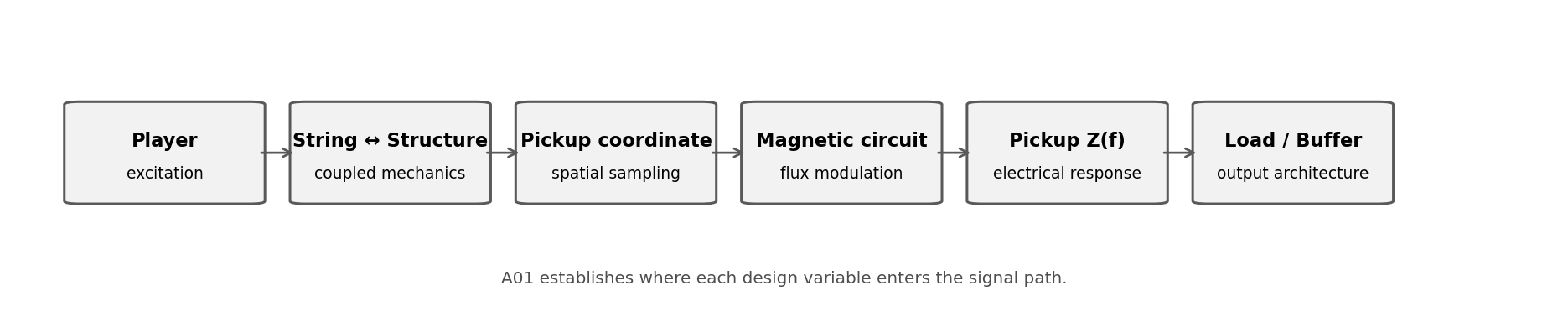
따라서 기존의 `material → vibration → pickup → output`은 내부 shorthand로 유지할 수 있지만, 실제 설계·측정 문서에서는 `excitation → coupled string/structure dynamics → pickup-coordinate sampling → magnetic transduction → pickup impedance → electrical loading → output`으로 확장한다.
2. String — 이상적인 정상파에서 실제 악기 현으로
2.1 Ideal stretched string — scale, tension, linear density
이상적인 유연한 현에서 횡진동의 파동속도는 c = √(T/μ)이고, speaking length가 L일 때 고유주파수는 fₙ = (n/2L)√(T/μ)로 표현된다. 여기서 T는 tension, μ는 linear mass density, n은 mode number다 [1]. 이 식은 동일한 pitch 조건에서 scale length·string mass·tension이 어떻게 연결되는지 보여주는 RavenForge의 mechanical baseline이다.
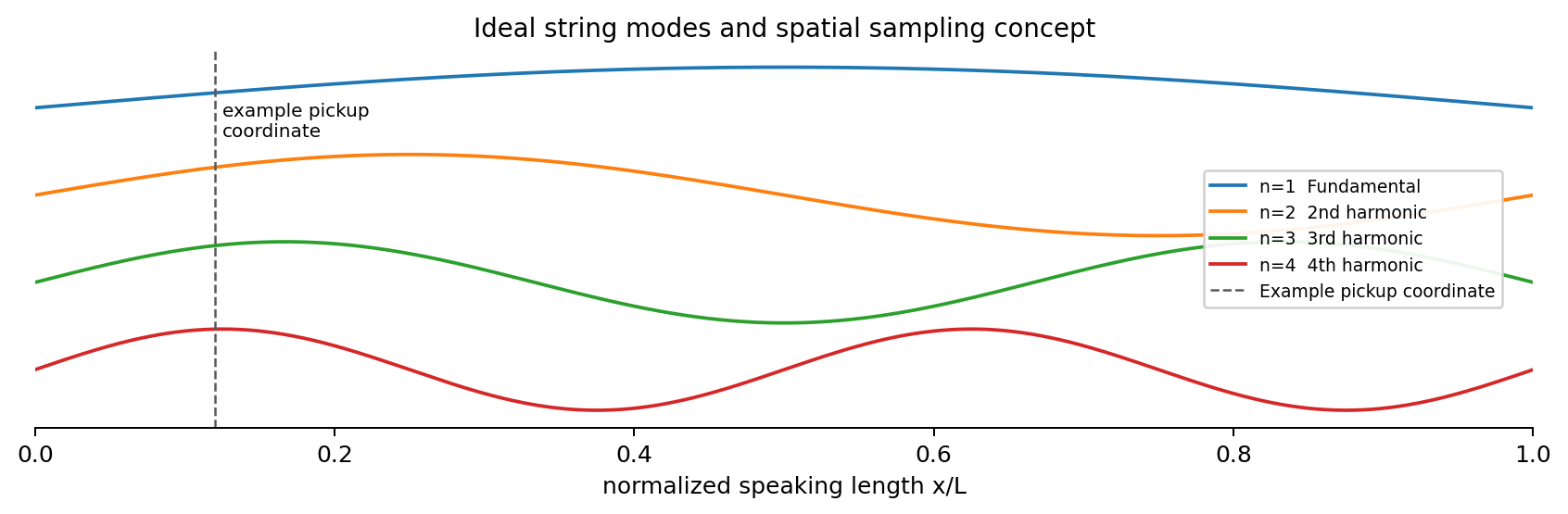
이상적인 mode shape는 sin(nπx/L)로 나타낼 수 있으며 각 partial마다 node와 antinode의 위치가 달라진다. 따라서 현의 “전체 소리”는 공간 어디에서나 동일하지 않다.
Figure 2. 이상적인 string mode와 pickup spatial sampling의 기본 개념. Idealized point-sampling schematic. 실제 pickup은 finite sensing width와 nonuniform magnetic field를 가진다 [1,5,6]. |
2.2 Real string — stiffness, damping, termination
실제 steel guitar/bass string은 ideal flexible string이 아니다. bending stiffness, core/wrap construction, 내부·공기 감쇠, fret/nut/bridge termination, 구조물과의 coupling 때문에 partial frequency와 decay가 이상모델에서 벗어날 수 있다. 특히 stiffness는 partial을 정확한 정수배에서 벗어나게 하는 inharmonicity를 만든다 [1].
Design rule |
3. String–Structure Coupling — boundary condition이면서 energy sink
현의 양 끝은 이상적인 fixed point가 아니다. bridge와 nut/fret를 통해 neck·body·hardware가 움직일 수 있고, 특정 주파수에서 구조의 mobility가 높으면 현의 에너지가 구조로 더 강하게 전달된다. driving-point mechanical admittance는 Y(ω)=V(ω)/F(ω)로 표현할 수 있으며, conductance Re{Y}는 구조로 전달·소산되는 에너지와 연결된다 [2,3].
Paté, Le Carrou & Fabre는 solid-body electric guitar의 decay를 isolated-string damping과 neck coupling을 결합해 예측했고, Fleischer는 dead spot에서 neck conductance가 높은 주파수와 짧은 string decay의 관계를 측정했다 [2,3]. 이것은 “목재가 pickup으로 직접 들어간다”는 설명보다 `material + geometry + joint + hardware → structural admittance → string modal amplitude/decay`라는 경로가 더 방어 가능함을 보여준다.
Design rule |
4. Pickup Position — tone adjective가 아니라 spatial sampling coordinate
자기 픽업은 air pressure나 body vibration을 직접 측정하는 마이크가 아니다. magnetic field 안에서 움직이는 ferromagnetic string의 운동을 감지한다. 이상적인 point sensor라면 n번째 mode의 위치계수는 Hpos(n,xp) ∝ sin(nπxp/L)로 생각할 수 있다 [5,6]. 따라서 특정 harmonic node 부근에 pickup이 놓이면 그 성분은 상대적으로 억제될 수 있다.
이 관점에서 “bridge pickup은 밝다”는 표현은 결과를 묘사하는 shorthand일 뿐 설계변수 자체가 아니다. bridge 쪽으로 이동하면 fundamental과 저차 partial의 displacement가 상대적으로 작아지는 조건이 생기고 upper-partial ratio가 달라질 수 있다. 실제 연구에서도 pickup position과 plucking point가 spectrum에 강한 signature를 남긴다 [5,6].
A01 scope |
5. Magnetic Pickup — mechanical domain에서 electrical domain으로
자기 픽업은 A01 signal chain에서 electromechanical transducer다. Faraday relation은 e(t) = −N·dΦ/dt로 쓸 수 있지만, 실제 기타 pickup을 단순한 “금속 현이 코일 옆에서 움직여 전기를 만든다”는 수준으로 축소하면 자기회로의 구조를 놓친다. permanent magnet, pole/blade, ferromagnetic string과 coil이 하나의 magnetic system을 이루며, 현 위치 변화가 coil-linked flux를 변화시킨다 [4,7].
Horton & Moore는 pickup response의 위치 의존성과 비선형성을 모델링했고, Lemarquand & Lemarquand는 permanent-magnet pickup의 magnetic circuit을 계산 대상으로 다뤘다 [4,7]. 충분히 강하고 가까운 magnet은 string motion에 back-action을 가할 수 있으므로 pickup을 완전히 비침습적 센서로 간주하지 않는다.
Design rule |
6. Electrical Boundary — 유도전압 이후에는 impedance 문제다
유도 EMF가 생성된 뒤에는 pickup coil의 resistance, inductance, winding/self capacitance가 electrical transfer function을 형성하고, 여기에 pot·tone network·cable capacitance·amp/buffer input impedance가 결합한다. 따라서 pickup output은 “Faraday voltage” 그대로가 아니다 [5,8].
최근 controlled winding study에서는 같은 기본 magnetic architecture 안에서 turns와 wire gauge를 변화시키자 self-resonant frequency와 impedance peak가 함께 변했다 [8]. 즉 DCR 하나로 pickup의 brightness, output, resonance를 대체해서는 안 된다.
A01 boundary |
7. RavenForge Signal Model — domain을 섞지 않는 설계 구조
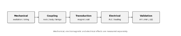
Figure 3. Mechanical / electromagnetic / electrical domain의 분리.
RavenForge measurement architecture derived from A01 literature review.
Stage | Domain | Design variable | Measure | Next log |
Excitation | Mechanical | pluck point / displacement / force | initial level, attack spectrum | C01 |
String | Mechanical | L, T, μ, gauge, stiffness | f0, harmonic ratios, inharmonicity | A01 / C01 |
String ↔ structure | Mechanical coupling | neck/body/bridge, joint, reinforcement | FRF, admittance, conductance, decay | Material Log / C01 |
Spatial sampling | Sensing geometry | pickup coordinate, sensing width | harmonic ratio, null map | A02 / C01 |
Magnetic circuit | Electromagnetic | magnet, pole/blade, string gap | sensitivity, nonlinearity, pull | A01 / A03 |
Pickup coil | Electrical | turns, gauge, topology | DCR, complex Z(f), self resonance | A03 |
Loading | Electrical | pot, cable C, input Z | loaded response, Q, transfer function | A04 / C02 |
Buffer / preamp | Electrical | Zin, Zout, gain | isolation, cable dependence | A05 |
8. RavenForge Application — ASKR, EMBLA, future 3PU
8.1 ASKR — bridge-near pickup을 target response로 다시 정의한다
ASKR의 공격적인 성격은 “pickup을 최대한 bridge 쪽에 둔다”는 관습으로 끝내지 않는다. A02/C01에서 fundamental suppression, upper-partial ratio, harmonic null avoidance와 attack spectrum을 target으로 정의한 뒤 coordinate를 역산한다. 즉 `concept → target response → pickup coordinate`가 된다.
8.2 EMBLA — passive / buffered architecture를 loading 문제로 본다
EMBLA에서 passive/active의 차이는 단순한 preamp 유무가 아니다. passive high-impedance pickup은 cable/load interaction이 voicing의 일부가 될 수 있고, pickup 직후 high-Z buffer를 두면 downstream cable의 영향을 크게 분리할 수 있다. 따라서 C02/A05에서 “남길 loading character”와 “제거할 variability”를 구분한다.
8.3 Future 3PU — 세 pickup을 서로 다른 spectral sampler로 설계한다
향후 3PU layout은 neck/middle/bridge라는 관습적 명칭보다 normalized coordinate, harmonic-null overlap, spectral complementarity를 기준으로 배치한다. 동일 string의 서로 다른 공간 샘플러라는 관점이 multi-pickup architecture의 출발점이다.
9. Evidence Matrix — A01에서 어디까지 주장할 수 있는가
Claim | Assessment | Evidence | RavenForge wording |
f0는 L, T, μ와 연결된다 | Supported | Standard string physics [1] | Mechanical baseline |
실제 steel string은 ideal harmonic series에서 벗어날 수 있다 | Supported | String stiffness / damping literature [1] | Record inharmonicity and partial decay |
구조 공진은 string decay를 바꿀 수 있다 | Supported | JASA conductance/decay studies [2,3] | Measure FRF/admittance |
목재가 pickup으로 직접 신호를 전달한다 | Incorrect framing | Pickup senses string motion [2,4,5] | Use string–structure coupling path |
pickup position은 spectrum을 바꾼다 | Supported | Pickup modeling / estimation [5,6] | Coordinate is a design variable |
magnetic pickup은 완전한 linear displacement sensor다 | Not generalizable | Nonlinear pickup modeling [4] | Control gap and magnetic geometry |
DCR만으로 pickup tone을 예측할 수 있다 | Not supported | Impedance / winding data [5,8] | Measure Z(f), not DCR alone |
pot/cable loading은 passive response를 바꾼다 | Supported | Pickup circuit modeling [5] | A04/C02 validation |
현재 ASKR 좌표가 최적이다 | Not established | RavenForge data pending | C01 required |
EMBLA에 특정 buffer topology가 최적이다 | Not established | RavenForge data pending | A05 required |
10. A01-derived Prototype Measurement Protocol
문헌은 각 물리 경로가 존재한다는 근거를 제공하지만 RavenForge prototype의 정답을 대신하지 않는다. 따라서 A01 이후에는 독립변수를 한 domain씩 바꾸고 나머지를 고정한다.
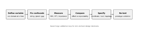
Figure 4. A01-derived RavenForge validation loop.
RavenForge experimental workflow. Effect size must exceed repeatability error before a variable becomes a specification.
Stage | Record | Decision |
Baseline setup | string brand/gauge, tuning, scale, pickup gap, pluck coordinate | test condition lock |
Gauge R&R | same condition repeated 20–30× | measurement noise floor |
Mechanical FRF | neck/bridge conductance, modal frequency, damping | structure-coupling map |
Pickup position sweep | fixed load/gap/pluck, coordinate sweep | A02/C01 coordinate candidates |
Pickup Z(f) | isolated complex impedance sweep | A03 equivalent model |
Loading sweep | 250k / 500k / 1M / cable-C / direct buffer | A04/C02 load decision |
Buffer comparison | passive direct vs immediate buffer | A05 topology decision |
Assembled prototype | DI FFT, partial decay, noise, repeatability | specification revision |
Measurement rule
2–5 mm pickup 이동이나 loading 차이가 repeatability error보다 작다면 RavenForge specification으로 채택하지 않는다. 먼저 측정 시스템의 noise floor를 확정한다.
11. 현재 결론 — 악기는 coupled signal system이다
A01의 목적은 새로운 “톤의 서열”을 만드는 것이 아니다. 전기 현악기의 출력은 player excitation, coupled string/structure dynamics, spatial sampling, magnetic transduction, pickup impedance와 external loading이 연속적으로 결합한 결과다. 따라서 material, pickup position, magnet, winding, pot과 cable을 같은 종류의 tone variable로 한 표에 섞지 않는다. 각 요소는 서로 다른 causal position과 측정법을 가진다.
Current design position |
RavenForge의 기존 shorthand `material → vibration → pickup → output`은 앞으로 실제 연구 문서에서 `excitation → coupled string/structure dynamics → pickup-coordinate sampling → magnetic transduction → pickup impedance → electrical loading → output`으로 확장한다.
12. Next Research — A01 이후의 역할 분담
Code | Research question | A01에서 넘기는 변수 |
A02 | Pickup Position and Harmonic Sampling | normalized coordinate, node/null, finite sensing width |
B02 | Voicing Before Specification | target response를 specification으로 역산 |
A03 | Magnetic Pickups as RLC Systems | DCR, L, C, Z(f), resonance, Q |
A04 | Electrical Loading of Passive Pickups | pot, cable capacitance, input impedance |
C01 | Pickup Position FFT Mapping | A02 spatial model validation |
C02 | Pickup Loading Measurement | A04 loaded-response validation |
A05 | Active Buffers and Input Impedance | high-Z sensing / low-Z output isolation |
References
[1] Fletcher, N. H.; Rossing, T. D. The Physics of Musical Instruments. Springer. Stretched-string vibration, normal modes and musical-acoustics reference.
[2] Paté, A.; Le Carrou, J.-L.; Fabre, B. “Predicting the Decay Time of Solid Body Electric Guitar Tones.” Journal of the Acoustical Society of America 135(5), 3045–3055 (2014). DOI: 10.1121/1.4871360.
[3] Fleischer, H. “Diagnosing dead spots of electric guitars and basses by measuring the mechanical conductance.” Journal of the Acoustical Society of America 105(2) (1999). DOI: 10.1121/1.426224.
[4] Horton, N. G.; Moore, T. R. “Modeling the Magnetic Pickup of an Electric Guitar.” American Journal of Physics 77, 144–150 (2009).
[5] Paiva, R. C. D.; Pakarinen, J.; Välimäki, V. “Acoustics and Modeling of Pickups.” Journal of the Audio Engineering Society 60(10), 768–782 (2012).
[6] Mohamad, S.; Dixon, S.; Harte, C. “Pickup Position and Plucking Point Estimation on an Electric Guitar via Autocorrelation.” Journal of the Acoustical Society of America 142 (2017).
[7] Lemarquand, G.; Lemarquand, V. “Calculation Method of Permanent-Magnet Pickups for Electric Guitars.” IEEE Transactions on Magnetics 43 (2007).
[8] Batchelor et al. “Guitar Pickups I: Analysis of the Effect of Winding and Wire Gauge on Single Coil Electric Guitar Pickups.” Controlled experimental pickup study; treated as recent/preprint evidence below established textbook/JASA/IEEE/JAES sources.
[R1] RavenForge / Material & Acoustics Research Log 01. “Tonewood as a Structural Variable.” 2026.09.01.
[R2] RavenForge internal A01 deep-research working report. “전기 현악기 신호 전달 모델.” 2026.09.05.
Source-status note |
Working research document · 2026.09.05