RAVENFORGE / SIGNAL & TRANSDUCTION RESEARCH LOG — A01
RAVENFORGE
Signal & Transduction Research Log
A01 — From Mechanical Vibration to Electrical Signal
From string–structure coupling to magnetic transduction and electrical output
Document Purpose |
Code | A01 |
Focus | String vibration · mechanical coupling · pickup spatial sampling · magnetic transduction · electrical boundary |
Evidence | Musical acoustics · JASA / JAES / IEEE pickup studies · controlled electric-guitar experiments |
RavenForge link | material → vibration → pickup → output signal model |
Downstream logs | A02 / A03 / A04 / C01 / C02 / A05 |
Status | Literature framework established · prototype validation pending |
1. Research Question — Where Does the Signal of an Electric Instrument Begin, and Where Is It Altered?
The final output of an electric guitar or bass is not generated independently by any single component. When the player imparts an initial displacement and velocity to the string, the string vibrates under the conditions set by tension, length, linear mass density, and stiffness, while exchanging energy with the neck/body structure through the nut/fret and bridge. Components of the resulting string motion at the pickup location alter the magnetic circuit and induce a voltage in the coil. Pickup impedance and control/cable/input loading then reshape the frequency response [1–7].
Key Perspective |
Figure 1. RavenForge signal chain defined in A01. RavenForge schematic · literature framework based on Fletcher & Rossing, Paté et al., Horton & Moore, Paiva et al. [1–6]. |
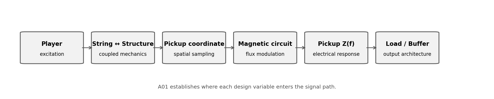
The existing `material → vibration → pickup → output` chain can therefore remain as an internal shorthand, but design and measurement documents expand it to `excitation → coupled string/structure dynamics → pickup-coordinate sampling → magnetic transduction → pickup impedance → electrical loading → output`.
2. String — From Ideal Standing Waves to Real Instrument Strings
2.1 Ideal Stretched String — Scale, Tension, Linear Density
For an ideal flexible string, the transverse-wave velocity is c = √(T/μ), and when the speaking length is L the natural frequencies are expressed as fₙ = (n/2L)√(T/μ). Here, T is tension, μ is linear mass density, and n is the mode number [1]. This relation is RavenForge’s mechanical baseline for understanding how scale length, string mass, and tension are linked at a given pitch.
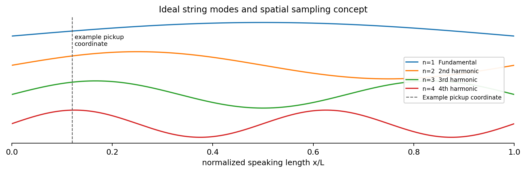
An ideal mode shape can be represented by sin(nπx/L), with each partial having different node and antinode locations. The string’s “entire sound” is therefore not identical at every point in space.
Figure 2. Basic concept of ideal string modes and pickup spatial sampling. Idealized point-sampling schematic. Real pickups have finite sensing width and a nonuniform magnetic field [1,5,6]. |
2.2 Real String — Stiffness, Damping, Termination
A real steel guitar/bass string is not an ideal flexible string. Bending stiffness, core/wrap construction, internal and aerodynamic damping, fret/nut/bridge termination, and coupling to the instrument structure can cause partial frequencies and decay to depart from the ideal model. Stiffness in particular produces inharmonicity by shifting partials away from exact integer multiples [1].
Design rule |
3. String–Structure Coupling — Boundary Condition and Energy Sink
The two ends of the string are not ideal fixed points. The neck, body, and hardware can move through the bridge and nut/fret terminations, and when structural mobility is high at a given frequency, string energy can be transferred more strongly into the structure. Driving-point mechanical admittance can be written as Y(ω)=V(ω)/F(ω), while the conductance Re{Y} is related to energy transferred into and dissipated by the structure [2,3].
Paté, Le Carrou & Fabre predicted the decay of solid-body electric-guitar tones by combining isolated-string damping with neck coupling, while Fleischer measured the relationship between high neck conductance at dead spots and short string decay [2,3]. This supports `material + geometry + joint + hardware → structural admittance → string modal amplitude/decay` as a more defensible path than the claim that “wood goes directly into the pickup.”
Design rule |
4. Pickup Position — A Spatial-Sampling Coordinate, Not a Tone Adjective
A magnetic pickup is not a microphone that directly measures air pressure or body vibration. It senses the motion of a ferromagnetic string moving within a magnetic field. For an ideal point sensor, the position coefficient of the nth mode can be approximated as Hpos(n,xp) ∝ sin(nπxp/L) [5,6]. A pickup located near the node of a given harmonic can therefore suppress that component relative to others.
From this perspective, “the bridge pickup is bright” is only shorthand for a result, not the design variable itself. Moving toward the bridge creates conditions in which the displacement of the fundamental and lower partials becomes relatively smaller, altering the upper-partial ratio. Experimental studies likewise show that pickup position and plucking point leave strong signatures in the spectrum [5,6].
A01 scope |
5. Magnetic Pickup — From the Mechanical Domain to the Electrical Domain
The magnetic pickup is the electromechanical transducer in the A01 signal chain. Faraday’s relation can be written as e(t) = −N·dΦ/dt, but reducing a real guitar pickup to “a metal string moving beside a coil to generate electricity” omits the structure of the magnetic circuit. The permanent magnet, pole/blade, ferromagnetic string, and coil form a single magnetic system, and changes in string position alter the coil-linked flux [4,7].
Horton & Moore modeled the position dependence and nonlinearity of pickup response, while Lemarquand & Lemarquand treated the magnetic circuit of permanent-magnet pickups as a calculable system [4,7]. A sufficiently strong and close magnet can exert back-action on string motion, so the pickup should not be treated as a completely non-invasive sensor.
Design rule |
6. Electrical Boundary — After Induced Voltage, the Problem Is Impedance
Once an induced EMF has been generated, the pickup coil’s resistance, inductance, and winding/self capacitance form an electrical transfer function, to which the pot, tone network, cable capacitance, and amp/buffer input impedance are added. The pickup output is therefore not simply the “Faraday voltage” itself [5,8].
In a recent controlled winding study, changing the turn count and wire gauge within the same basic magnetic architecture shifted both the self-resonant frequency and the impedance peak [8]. DCR alone should therefore not be used as a proxy for pickup brightness, output, or resonance.
A01 boundary |
7. RavenForge Signal Model — A Design Structure That Keeps Domains Separate
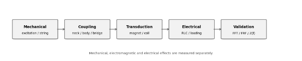
Figure 3. Mechanical / electromagnetic / electrical domain의 분리.
RavenForge measurement architecture derived from A01 literature review.
Stage | Domain | Design variable | Measure | Next log |
Excitation | Mechanical | pluck point / displacement / force | initial level, attack spectrum | C01 |
String | Mechanical | L, T, μ, gauge, stiffness | f0, harmonic ratios, inharmonicity | A01 / C01 |
String ↔ structure | Mechanical coupling | neck/body/bridge, joint, reinforcement | FRF, admittance, conductance, decay | Material Log / C01 |
Spatial sampling | Sensing geometry | pickup coordinate, sensing width | harmonic ratio, null map | A02 / C01 |
Magnetic circuit | Electromagnetic | magnet, pole/blade, string gap | sensitivity, nonlinearity, pull | A01 / A03 |
Pickup coil | Electrical | turns, gauge, topology | DCR, complex Z(f), self resonance | A03 |
Loading | Electrical | pot, cable C, input Z | loaded response, Q, transfer function | A04 / C02 |
Buffer / preamp | Electrical | Zin, Zout, gain | isolation, cable dependence | A05 |
8. RavenForge Application — ASKR, EMBLA, Future 3PU
8.1 ASKR — Reframing the Bridge-Near Pickup as a Target-Response Problem
ASKR’s aggressive character is not reduced to the convention of “placing the pickup as close to the bridge as possible.” A02/C01 first define fundamental suppression, upper-partial ratio, harmonic-null avoidance, and attack spectrum as target responses, then derive the coordinate from those targets. In other words: `concept → target response → pickup coordinate`.
8.2 EMBLA — Treating Passive / Buffered Architecture as a Loading Problem
In EMBLA, the difference between passive and active is not simply whether a preamp is present. With a passive high-impedance pickup, cable/load interaction can become part of the voicing, while a high-Z buffer placed immediately after the pickup can largely isolate the downstream cable. C02/A05 therefore distinguish the “loading character to retain” from the “variability to remove.”
8.3 Future 3PU — Designing the Three Pickups as Distinct Spectral Samplers
Future 3PU layouts will be positioned according to normalized coordinate, harmonic-null overlap, and spectral complementarity rather than the conventional neck/middle/bridge labels. Treating the three pickups as distinct spatial samplers of the same string is the starting point for a multi-pickup architecture.
9. Evidence Matrix — What Can A01 Support?
Claim | Assessment | Evidence | RavenForge wording |
f0 is linked to L, T, and μ | Supported | Standard string physics [1] | Mechanical baseline |
A real steel string can depart from the ideal harmonic series | Supported | String stiffness / damping literature [1] | Record inharmonicity and partial decay |
Structural resonances can alter string decay | Supported | JASA conductance/decay studies [2,3] | Measure FRF/admittance |
Wood directly transmits a signal into the pickup | Incorrect framing | Pickup senses string motion [2,4,5] | Use string–structure coupling path |
Pickup position changes the spectrum | Supported | Pickup modeling / estimation [5,6] | Coordinate is a design variable |
A magnetic pickup is a perfectly linear displacement sensor | Not generalizable | Nonlinear pickup modeling [4] | Control gap and magnetic geometry |
Pickup tone can be predicted from DCR alone | Not supported | Impedance / winding data [5,8] | Measure Z(f), not DCR alone |
Pot/cable loading changes passive response | Supported | Pickup circuit modeling [5] | A04/C02 validation |
The current ASKR coordinate is optimal | Not established | RavenForge data pending | C01 required |
A specific buffer topology is optimal for EMBLA | Not established | RavenForge data pending | A05 required |
10. A01-Derived Prototype Measurement Protocol
The literature establishes that these physical pathways exist, but it does not provide the final answer for a RavenForge prototype. After A01, one independent variable is therefore changed within one domain at a time while the remaining conditions are held fixed.
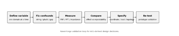
Figure 4. A01-derived RavenForge validation loop.
RavenForge experimental workflow. Effect size must exceed repeatability error before a variable becomes a specification.
Stage | Record | Decision |
Baseline setup | string brand/gauge, tuning, scale, pickup gap, pluck coordinate | test condition lock |
Gauge R&R | same condition repeated 20–30× | measurement noise floor |
Mechanical FRF | neck/bridge conductance, modal frequency, damping | structure-coupling map |
Pickup position sweep | fixed load/gap/pluck, coordinate sweep | A02/C01 coordinate candidates |
Pickup Z(f) | isolated complex impedance sweep | A03 equivalent model |
Loading sweep | 250k / 500k / 1M / cable-C / direct buffer | A04/C02 load decision |
Buffer comparison | passive direct vs immediate buffer | A05 topology decision |
Assembled prototype | DI FFT, partial decay, noise, repeatability | specification revision |
Measurement rule
If the effect of a 2–5 mm pickup movement or a loading change is smaller than the repeatability error, it is not adopted as a RavenForge specification. Establish the measurement system’s noise floor first.
11. Current Conclusion — The Instrument Is a Coupled Signal System
A01 is not intended to create a new hierarchy of “tone.” The output of an electric string instrument is the result of player excitation, coupled string/structure dynamics, spatial sampling, magnetic transduction, pickup impedance, and external loading acting in sequence. Material, pickup position, magnet, winding, pot, and cable are therefore not grouped together as the same kind of tone variable. Each occupies a different causal position and requires a different measurement method.
Current design position |
RavenForge’s existing shorthand `material → vibration → pickup → output` will henceforth be expanded in research documents to `excitation → coupled string/structure dynamics → pickup-coordinate sampling → magnetic transduction → pickup impedance → electrical loading → output`.
12. Next Research — Division of Roles After A01
Code | Research question | Variable handed off from A01 |
A02 | Pickup Position and Harmonic Sampling | normalized coordinate, node/null, finite sensing width |
B02 | Voicing Before Specification | Derive the specification backward from the target response |
A03 | Magnetic Pickups as RLC Systems | DCR, L, C, Z(f), resonance, Q |
A04 | Electrical Loading of Passive Pickups | pot, cable capacitance, input impedance |
C01 | Pickup Position FFT Mapping | A02 spatial model validation |
C02 | Pickup Loading Measurement | A04 loaded-response validation |
A05 | Active Buffers and Input Impedance | high-Z sensing / low-Z output isolation |
References
[1] Fletcher, N. H.; Rossing, T. D. The Physics of Musical Instruments. Springer. Stretched-string vibration, normal modes and musical-acoustics reference.
[2] Paté, A.; Le Carrou, J.-L.; Fabre, B. “Predicting the Decay Time of Solid Body Electric Guitar Tones.” Journal of the Acoustical Society of America 135(5), 3045–3055 (2014). DOI: 10.1121/1.4871360.
[3] Fleischer, H. “Diagnosing dead spots of electric guitars and basses by measuring the mechanical conductance.” Journal of the Acoustical Society of America 105(2) (1999). DOI: 10.1121/1.426224.
[4] Horton, N. G.; Moore, T. R. “Modeling the Magnetic Pickup of an Electric Guitar.” American Journal of Physics 77, 144–150 (2009).
[5] Paiva, R. C. D.; Pakarinen, J.; Välimäki, V. “Acoustics and Modeling of Pickups.” Journal of the Audio Engineering Society 60(10), 768–782 (2012).
[6] Mohamad, S.; Dixon, S.; Harte, C. “Pickup Position and Plucking Point Estimation on an Electric Guitar via Autocorrelation.” Journal of the Acoustical Society of America 142 (2017).
[7] Lemarquand, G.; Lemarquand, V. “Calculation Method of Permanent-Magnet Pickups for Electric Guitars.” IEEE Transactions on Magnetics 43 (2007).
[8] Batchelor et al. “Guitar Pickups I: Analysis of the Effect of Winding and Wire Gauge on Single Coil Electric Guitar Pickups.” Controlled experimental pickup study; treated as recent/preprint evidence below established textbook/JASA/IEEE/JAES sources.
[R1] RavenForge / Material & Acoustics Research Log 01. “Tonewood as a Structural Variable.” 2026.09.01.
[R2] RavenForge internal A01 deep-research working report. “Electric String Instrument Signal-Transfer Model.” 2026.09.05.
Source-status note |
Working research document · 2026.09.05